Isuzu Trooper (2000 year). Manual - part 32


  Index      Isuzu     Isuzu Trooper - service repair manual 2000 year


Search            


Content   ..  30  31  32  33   ..


Isuzu Trooper (2000 year). Manual - part 32


HEATING, VENTILATION AND AIR CONDITIONING (HVAC) 1A–97

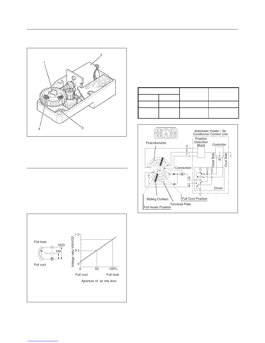
The actuator changes the motor speed using the gear
and drives each door rotating the output axis united with
the sliding contact.

860RW026

Legend

(1) Output Axis
(2) Motor
(3) Printed Circuit Board
(4) Sliding Contact

The mode and mix actuators are common actuators with
the built–in potentiometer.  For the intake actuator, the
contact switch type is selected.
The potentiometer is a register assembled to the printed
circuit board of the mix and mode actuators.  It detects the
air mix door position specified by rotation of the output
axis as a ratio of the variable terminal (VM) voltage
against the reference voltage (VDD: 5V), then signals the
value to the automatic heater/air conditioner control unit.

C01RX016

Movement of Mix Actuator

Position of the air mix door is determined by the controller
on the automatic heater/air conditioner control unit.
As the heat or cool side of the controller is grounded, the
transistor on the driver is activated and, thus, the motor
rotation is turned on.  The sliding contact connected to the
motor sends the position detection signal from the
potentiometer to the automatic heater/air conditioner
control unit.  As the set temperature and interior
temperature are balanced, the controller returns to the
neutral and the motor rotation is stopped.

I-45

Rotation

direction

Remarks

(+) side

(-) side

direction

8

6

Clockwise

Full heat side

6

8

Counter

clockwise

Full cool side

C01RX005

1A–98 HEATING, VENTILATION AND AIR CONDITIONING (HVAC)

Movement of Mode Actuator

As target position of the mode door is decided on the
controller of the control unit, the control unit reads the
position detection signal from the actuator to select the
clockwise or counter clockwise motor rotation direction.
Grounding the controller VENT or DEF side after the
direction selection activates the transistor on the driver,
thus turning on the motor rotation.  Accompanying the
motor rotation, the sliding contact rotates, too.  When the
target position is reached, the controller on the control
unit returns to the neutral and the motor stops.

Conduction pin

Rotation

direction

Remarks

(+) side

(-) side

direction

5

1

Clockwise

VENT to DEF

direction

1

5

Counter

clockwise

DEF to VENT

direction

C01RX017

Movement of Intake Actuator

The controller on the automatic heater/air conditioner
control unit selects an intake mode to be used.
As the Terminal No.5 I-49 is grounded via the sliding
contact on the terminal plate, the transistor on the driver is
activated, thus turning on the motor rotation.  Then,
accompanying move of the motor, the sliding contact
rotates until grounding of the Terminal No.5 I-49 is
removed, thus stopping the motor.

Grounding ter-

minal

Rotation direc-

tion

Remarks

No.5 I-49

Clockwise

RE-CIRCULA-

TION

MIX

F

RESH

C01RX006

Overview of Automatic Control of
Automatic Air Conditioner

The full automatic heater and air conditioner on this
vehicle has the following features:

D

Interior temperature control.

D

Air flow control.

D

Mode (blow port) control.

D

Intake (switching between fresh air and interior air)
control.

D

Heater start timing control.

D

Cooler start timing control.

D

Evaporator anti-freeze control.

HEATING, VENTILATION AND AIR CONDITIONING (HVAC) 1A–99

Interior Temperature Control

The automatic heater/air conditioner control unit operates
on the setup temperature signal from the temperature
control switch and other sensor signals to derive the total
signal.  Then, the control unit compares this signal
against the signal from the potentiometer to determine
rotation direction of the mix actuator.  The mix actuator
moves the air mix door to the aperture specified by the
total signal so that the specified interior temperature is
achieved.
If the compressor is turned off in the A/C (air conditioning)
mode, aperture of the air mix door is offset according to
the outside air temperature or the specified interior
temperature.  This function removes the difference in the
blowing temperature in this state and that of when the
compressor is turned on.
When FH or FC is selected for the setup temperature, the
air mix door is accordingly fixed to the Full Heat or Full
Cool mode.
When the VENT mode is selected, aperture of the air mix
door is controlled so that excessively heated air may not
be blown from the VENT blow port.

C01RY00011

Air Flow Control

In the Auto Mode

D

The automatic heater/air conditioner control unit
operates on the setup temperature signal and other
sensor signals to derive the total signal.  Then, the
control unit adjusts base potential of the power
transistor to match it to the voltage pattern of the
target fan so that stage-less fan speed control can be
achieved.

When solar radiation quantity is detected in the VENT
or B/L mode, the control unit increases the minimum
fan voltage to offset.
When FH or FC is selected from the temperature
control switch, air flow is accordingly fixed to MAX HI or
AUTO HI.

In the Manual Mode

D

Air flow specified from the fan switch is entered to the
automatic heater/air conditioner control unit as the
manual signal.  The signal modifies the air flow to the
level specified from the fan switch so that the required
fan voltage is attained.

C01RY00008

1A–100 HEATING, VENTILATION AND AIR CONDITIONING (HVAC)

Mode (Blow Port) Control

The automatic heater/air conditioner control unit operates
on the setup temperature from the control switch, and
temperature and solar radiation quantify from the sensors
to determine the total mode control signal.  According to
the pattern specified by this signal, the control unit selects
either one of the VENT, BI-LEVEL, FOOT or DEF/FOOT
mode.
The mode actuator determines the rotation direction
comparing the target position against the current position
being determined by the position detection signal.
When FH or FC is selected for the temperature from the
temperature control switch, mode is accordingly fixed to
the VENT or FOOT.

D

In the manual operation of the mode switch, you can
select a desired blow port mode pressing the
corresponding mode switch.

D

Operating the DEF mode switch selects the DEF for
the blow port mode.

C01RY00009

Intake (Fresh air/interior air switching)
Control

In the Full Auto mode, the automatic heater/air
conditioner control unit operates on the setup
temperature signal and other sensor input signals to
derive the total signal.  According to the pattern specified
by this signal, the control unit provides the intake control.
When the fan is turned off or the A/C (air conditioning) is
turned off, the intake is fixed to the FRESH mode.
When FC or FH is selected from the control switch, the
intake mode is accordingly fixed to the RECIRC or
FRESH.

In the Manual Operation

D

Pressing the FRESH (fresh air intake) or the RECIRC
(room air circulation) accordingly selects the FRESH
or RECIRC mode.

When the DEF Mode Switch is depressed

D

The intake mode is fixed to the FRESH.  When the
MANU REC is selected, however, the mode is fixed
the RECIRC.

When the Mode Switch is depressed

D

If the automatic intake control is selected, the intake is
fixed to the currently selected mode.

C01RY00012


Content   ..  30  31  32  33   ..