Isuzu Trooper (2000 year). Manual - part 15


  Index      Isuzu     Isuzu Trooper - service repair manual 2000 year


Search            


Content   ..  13  14  15  16   ..


Isuzu Trooper (2000 year). Manual - part 15


HEATING, VENTILATION AND AIR CONDITIONING (HVAC) 1A–29
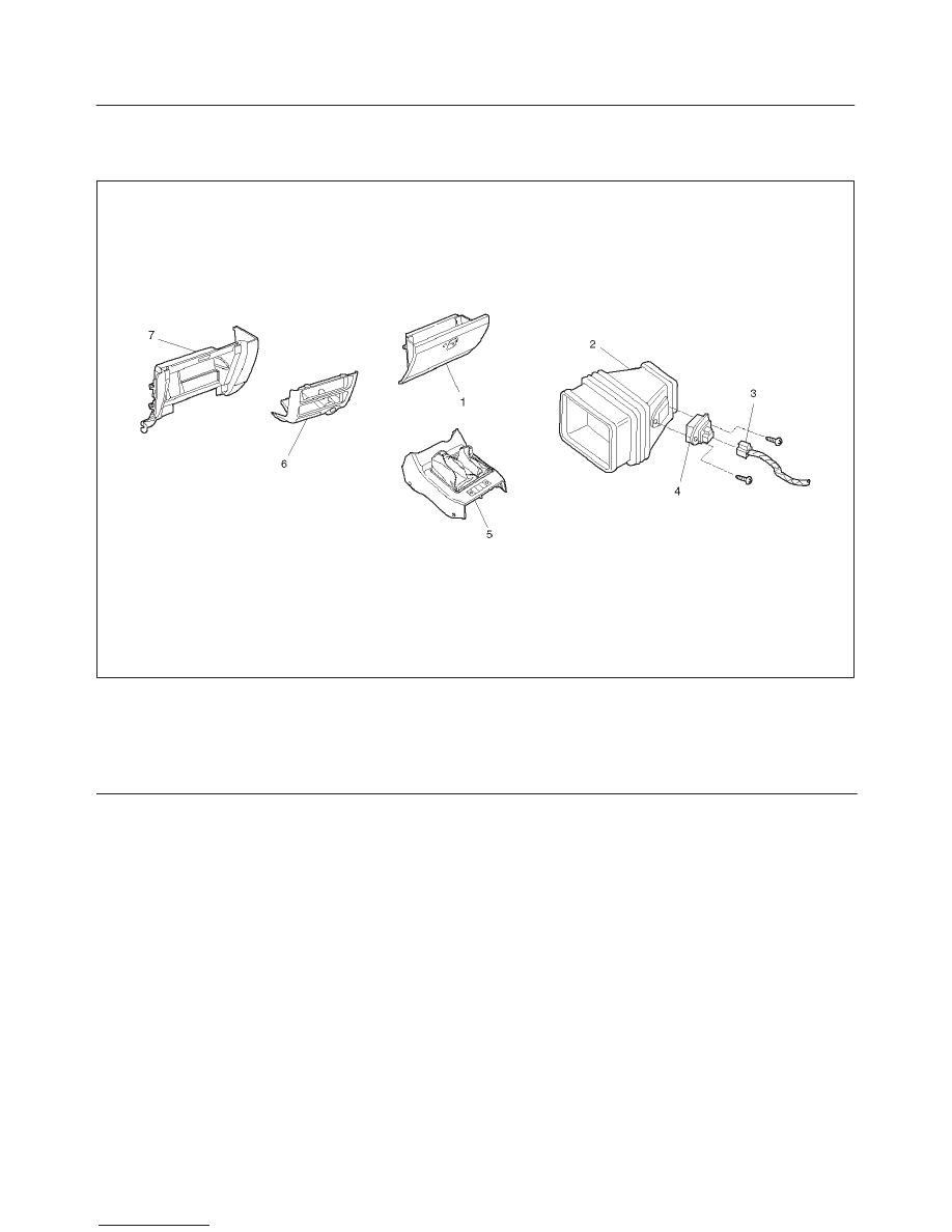
Resistor

Resistor and Associated Parts

874RW005

Legend

(1) Glove Box
(2) Duct (Heater only)
(3) Resistor Connector
(4) Resistor

(5) Front Console
(6) Lower Cluster
(7) Instrument Panel Passenger Lower Cover

Assembly

Removal

1. Disconnect the battery ground cable.
2. Remove front console.
3. Remove lower cluster.
4. Remove glove box.
5. Remove instrument panel passenger lower cover

assembly.

D

Refer to Instrument Panel Assembly in Body and
Accessories section.

6. Remove resistor connector.
7. Remove duct (heater only).
8. Remove resistor.

Installation

To install, follow the removal steps in the reverse order.

1A–30 HEATING, VENTILATION AND AIR CONDITIONING (HVAC)

Air Conditioning System

General Description

Air Conditioning Refrigerant Cycle Construction

C01RS003

Legend

(1) Electronic Thermostat
(2) Evaporator Core
(3) Evaporator Assembly
(4) Temperature Sensor
(5) Expansion Valve
(6) Blower Motor
(7) Dual Pressure Switch
(8) Receiver/Drier

(9) Condenser

(10) Compressor

(11) Magnetic Clutch

(12) Mode (HEAT) Control Door
(13) Temp. Control Door (Air Mix Door)
(14) Heater Core
(15) Mode (VENT) Control Door
(16) Heater Unit
(17) Mode (DEF) Control Door

The refrigeration cycle includes the following four
processes as the refrigerant changes repeatedly from
liquid to gas and back to liquid while circulating.

Evaporation

The refrigerant is changed from a liquid to a gas inside the
evaporator.  The refrigerant mist that enters the

HEATING, VENTILATION AND AIR CONDITIONING (HVAC) 1A–31

evaporator vaporizes readily. The liquid refrigerant
removes the required quantity of heat (latent heat of
vaporization) from the air around the evaporator core
cooling fins and rapidly vaporizes.  Removing the heat
cools the air, which is then radiated from the fins and
lowers the temperature of the air inside the vehicle.
The refrigerant liquid sent from the expansion valve and
the vaporized refrigerant gas are both present inside the
evaporator as the liquid is converted to gas.
With this change from liquid to gas, the pressure inside
the evaporator must be kept low enough for vaporization
to occur at a lower temperature.  Because of that, the
vaporized refrigerant is sucked into the compressor.

Compression

The refrigerant is compressed by the compressor until it is
easily liquefied at normal temperature.
The vaporized refrigerant in the evaporator is sucked into
the compressor.  This action maintains the refrigerant
inside the evaporator at a low pressure so that it can
easily vaporize, even at low temperatures close to
0

°

C(32

°

F).

Also, the refrigerant sucked into the compressor is
compressed inside the cylinder to increase the pressure
and temperature to values such that the refrigerant can
easily liquefy at normal ambient temperatures.

Condensation

The refrigerant inside the condenser is cooled by the
outside air and changes from gas to liquid.
The high temperature, high pressure gas coming from the
compressor is cooled and liquefied by the condenser with
outside air and accumulated in the receiver/drier. The
heat radiated to the outside air by the high temperature,
high pressure gas in the compressor is called heat of
condensation. This is the total quantity of heat (heat of
vaporization) the refrigerant removes from the vehicle
interior via the evaporator and the work (calculated as the
quantity of heat) performed for compression.

Expansion

The expansion valve lowers the pressure of the
refrigerant liquid so that it can easily vaporize.
The process of lowering the pressure to encourage
vaporization before the liquefied refrigerant is sent to the
evaporator is called expansion. In addition, the expansion
valve controls the flow rate of the refrigerant liquid while
decreasing the pressure.
That is, the quantity of refrigerant liquid vaporized inside
the evaporator is determined by the quantity of heat which
must be removed at a prescribed vaporization
temperature. It is important that the quantity of refrigerant
be controlled to exactly the right value.

Compressor

The compressor performs two main functions:
It compresses low-pressure and low-temperature
refrigerant vapor from the evaporator into high-pressure
and high-temperature refrigerant vapor to the condenser.
It pumps refrigerant and refrigerant oil through the air
conditioning system.

This vehicle is equipped with six-cylinder axle plate
compressor (1).
The specified amount of the compressor oil is 240cc
(8.0 fl. oz.).
The oil used in the HFC-134a system compressor differs
from that used in R-12 systems.
Also, compressor oil to be used varies according to the
compressor model.  Be sure to avoid mixing two or more
different types of oil.
If the wrong oil is used, lubrication will be poor and the
compressor will seize or malfunction.
The magnetic clutch connector is a waterproof type.

Magnetic Clutch

The compressor is driven by the drive belt from the crank
pulley of the engine. If the compressor is activated each
time the engine is started, this causes too much load to
the engine. The magnetic clutch (3) transmits the power
from the engine to the compressor and activates it when
the air conditioning is ON. Also, it cuts off the power from
the engine to the compressor when the air conditioning is
OFF. Refer to Compressor in this section for magnetic
clutch repair procedure.

852RW002

Condenser

Also, it functions to cool and liquefy the high-pressure and
high-temperature vapor sent from the compressor by the
radiator fan or outside air.
A condenser may malfunction in two ways: it may leak, or
it may be restricted.  A condenser restriction will result in
excessive compressor discharge pressure.  If a partial
restriction is present, the refrigerant expands after
passing through the restriction.
Thus, ice or frost may form immediately after the
restriction. If air flow through the condenser or radiator is
blocked, high discharge pressures will result. During
normal condenser operation, the refrigerant outlet line will
be slightly cooler than the inlet line.
The vehicle is equipped with the parallel flow type
condenser. A larger thermal transmission area on the
inner surface of the tube allows the radiant heat to
increase and the ventilation resistance to decrease.

1A–32 HEATING, VENTILATION AND AIR CONDITIONING (HVAC)

The refrigerant line connection has a bolt at the block
joint, for easy servicing.
The condenser assembly (6) is located in front of the
radiator. It provides rapid heat transfer from the
refrigerant to the cooling fins.

875RW004

Receiver / Drier

The receiver/drier (5) performs four functions:

D

As the quantity of refrigerant circulated varies
depending on the refrigeration cycle conditions,
sufficient refrigerant is stored for the refrigeration
cycle to operate smoothly in accordance with
fluctuations in the quantity circulated.

D

The liquefied refrigerant from the condenser is mixed
with refrigerant gas containing air bubbles. If
refrigerant containing air bubbles. Is sent to the
expansion valve, the cooling capacity will decrease
considerably. Therefore, the liquid and air bubbles are
separated and only the liquid is sent to the expansion
valve.

D

The receiver/drier utilizes a filter and drier to remove
the dirt and water mixed in the cycling refrigerant.

D

The sight glass, installed on top of the receiver/drier,
shows the state of the refrigerant.

A receiver/drier may fail due to a restriction inside the
body of the unit. A restriction at the inlet to the
receiver/drier will cause high pressure.
Outlet restrictions will be indicated by low pressure and
little or no cooling. An excessively cold receiver/drier
outlet may indicate a restriction.
The receiver/drier of this vehicle is made of aluminum
with a smaller tank. It has a 300cc refrigerant capacity.
The refrigerant line connection has a bolt at the block
joint, for easy servicing.

875RW004

Pressure Switch

The pressure switch (Dual pressure switch) (4) is
installed on the upper part of the receiver/drier, to detect
excessively high pressure (high pressure switch) and
prevent compressor seizure due to the refrigerant leaking
(low pressure switch), so that the compressor is able to be
turned “ON” or “OFF”.
The pressure characteristics of HFC-134a refrigerant
differ from those of R-12. Thus, the pressure switch
operation for HFC-134a systems has been changed from
R-12.

Compressor

ON

(kPa/psi)

OFF

(kPa/psi)

Low-pressure

control

186.3

±

29.4

(27.0

±

4.3)

176.5

±

19.6

(25.6

±

2.8)

High-pressure

control

2353.6

±

196.1

(341.3

±

28.4)

2942.0

±

196.1

(426.6

±

28.4)

875RW004


Content   ..  13  14  15  16   ..