Isuzu Rodeo UE. Manual - part 643
9J1–9
RESTRAINT CONTROL SYSTEM
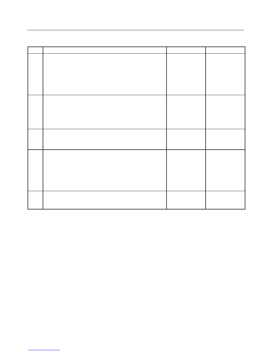
Chart B “AIR BAG” Warning Lamp Comes “ON” Steady
Step
Action
Yes
No
1
1. When measurements are requested in this chart use J–39200
DVM with correct terminal adapter from J–35616–A.
2. Ignition switch “OFF.”
3. Connect scan tool to data link connector, Follow directions as
given in the scan tool instruction manual.
4. Ignition switch “ON.”
5. Request SRS diagnostic trouble code display.
Does scan tool indicate “No Data Received”?
Go to Step 2
Go to Step 3
2
1. Ignition switch “OFF.”
2. Inspect SDM harness connector connection to SDM.
Is it securely connected to the SDM?
Ignition switch
“OFF.”
Replace SDM.
Go to Step 5
Connect SDM
securely to
de–activate
shorting clip in
SDM harness
connector.
Go to Step 5
3
Using scan tool, request SRS data list.
Is “ignition” more than 9 volts?
Go to Step 4
Ignition switch
“OFF.”
Replace SDM.
Go to Step 5
4
1. Ignition switch “OFF.”
2. Disconnect SRS coil and passenger air bag assemblies.
Yellow 2–pin connectors located at base of steering column
and behind the glove box assembly.
3. Disconnect SDM.
4. Measure resistance from SDM harness connector terminal “6”
to ground.
Does J–39200 display “0L” (infinite)?
Go to Chart A.
Replace SRS
harness.
Go to Step 5
5
Reconnect all SRS components, ensure all components are
properly mounted.
Was this step finished?
Repeat the “SRS
Diagnostic
System Check.”
Go to Step 5