Isuzu Rodeo UE. Manual - part 571


  Index      Isuzu     Isuzu Rodeo UE - service repair manual 1999 year


Search            


Content   ..  569  570  571  572   ..


Isuzu Rodeo UE. Manual - part 571


8D–132

WIRING SYSTEM

Diagnosis

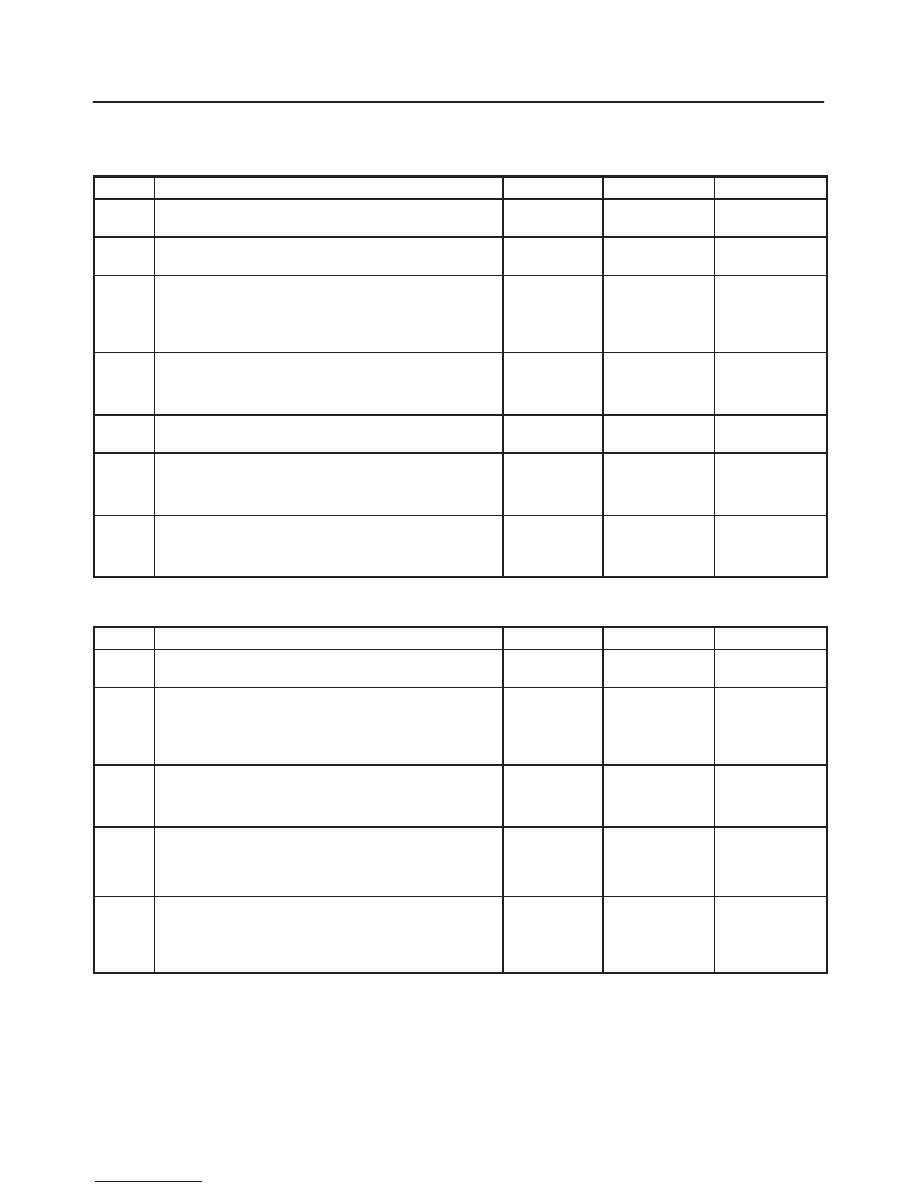
All The Doors Do Not Lock And Unlock By Door Lock SW–LH

Step

Action

Value(s)

Yes

No

1

Is the fuse 7 normlal?

Go to Step 2

Replace the

fuse

2

Is B–8 grounded securely?

Go to Step 3

Ground it

securely

3

Disconnect the front door lock and power window
switch–LH connector D–5.

Is there continuity between harness side connector
D–5 terminal 7 and the ground B–8?

Go to Step 5

Go to Step 4

4

Repair an open circuit between connector D–5 terminal
7 and the ground B–8.

Is the action complete?

Go to Step 3

5

Is the battery voltage applied between harness side
connector D–5 terminal 11 and the ground?

Approx. 12V

Go to Step 7

Go to Step 6

6

Repair an open circuit between the fuse 7 and
connector D–5 terminal 11.

Is the action complete?

Verify repair

7

Replace the front door lock & power window
switch–LH.

Is the action complete?

Verify repair

All The Doors Do Not Get Locked (Or Unlocked) By FRT Door Lock SW–RH

Step

Action

Value(s)

Yes

No

1

Is B–8 grounded securely?

Go to Step 2

Ground it

securely

2

Disconnect the front door lock and power window
switch–RH connector D–17.

Is there continuity between harness side connector
D–17 terminal 3 and the ground B–8?

Go to Step 4

Go to Step 3

3

Repair an open circuit between connector D–17
terminal 3 and the ground B–8.

Is the action complete?

Go to Step 2

4

Is there continuity between the front door lock & power
window switch–RH side connector D–17 terminal 7 and
3 with the switch turned to unlock position, and terminal
6 and 3 with the switch turned to lock position?

Go to Step 5

Replace the

switch

5

Repair an open circuit between the front door lock and
power window switch–LH and the front door lock and
power window switch–RH.

Is the action complete?

Verify repair

8D–133

WIRING SYSTEM

Door Lock Does Not Operate By Door Lock Key SW–LH

Step

Action

Value(s)

Yes

No

1

Disconnect the door lock key switch–LH connector
D–6.

Is there continuity between switch side connector D–6
terminal 4 and 3 with the switch turned to the lock side,
and switch side connector D–6 terminal 1 and 3 with the
switch turned to the unlock side?

Go to Step 2

Repair or

replace the

switch

2

Is there continuity between harness side connector
D–6 terminal 3 and the ground B–8?

Go to Step 4

Go to Step 3

3

Repair an open circuit between connector D–6 terminal
3 and the ground B–8.

Is the action complete?

Verify repair

4

Repair an open circuit between connector D–5 terminal
9 and connector D–6 terminal 4, and connector D–5
terminal 6 and connector D–6 terminal 1.

Is the action complete?

Verify repair

8D–134

WIRING SYSTEM

Power Window

General Description

The power window system consists of power window
switches and power window motors on driver and
passenger sides and power window relay.
With the starter switch in “ON” position, the battery
voltage is supplied through power window relay to the
power window switches on driver and passenger sides
Selection of up or down switch changes over the motor
rotating direction to open or close the window.
When the lock switch on the switch panel on the driver
side is pressed, the power window switch is in open state.
As a result, the power source to the other switches are cut
off, and the power window motors do not run.

8D–135

WIRING SYSTEM

Circuit Diagram–1

D08RW318


Content   ..  569  570  571  572   ..