Isuzu Rodeo UE. Manual - part 461


  Index      Isuzu     Isuzu Rodeo UE - service repair manual 1999 year


Search            


Content   ..  459  460  461  462   ..


Isuzu Rodeo UE. Manual - part 461


7A–60

AUTOMATIC TRANSMISSION (4L30–E)

252RW004

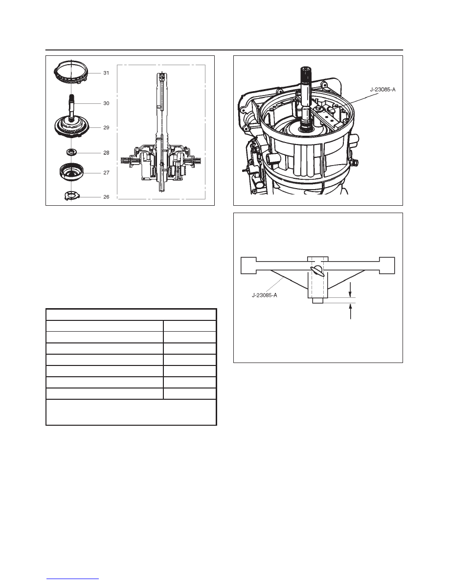
34. Overdrive clutch end play measurement

1. Install the J–23085–A selective washer gauging

tool on the adapter case flange and against the
input shaft.

2. Position the inner shaft of the tool against the

thrust surface of the overrun clutch housing.

3. Tighten thumb screw.  Remove the tool.

4. Measure gap.  Select appropriate size washer as

shown in the chart.

5. Set selective thrust washer aside.

Selective Thrust Washer

Gap:  mm(in)

Color

1.53 – 1.63 (0.060 – 0.064)

Yellow

1.72 – 1.82 (0.068 – 0.072)

Red

1.91 – 2.01 (0.075 – 0.079)

Black

2.10 – 2.20 (0.083 – 0.087)

Natural

2.29 – 2.39 (0.090 – 0.094)

Green

2.48 – 2.58 (0.098 – 0.102)

Blue

FOLLOWING THE PROCEDURE SHOULD 
RESULT IN FINAL END–PLAY FROM 0.1 mm TO
0.8 mm (0.004 in TO 0.03 in)

252RS005

252RS006

35. Install selective washer (32).

NOTE: Use petroleum jelly to hold selective washer in
place.

36. Install gasket (33).
37. Install converter housing and oil pump assembly (34)

to adapter case.

f

Fit and tighten seven outer 13 mm screws.

Torque: 39 N

m (29 lb ft)

7A–61

AUTOMATIC TRANSMISSION (4L30–E)

f

Ensure free rotation of pump using J–23082–01
pump rotation tool.

241RW010

38. Overdrive clutch end play measurement.

1. Fit J–25022 and J–24773–1 turbine shaft puller

on turbine shaft.

2. Position axial play checking tool on converter

housing mating face.

3. Pull turbine shaft upwards with puller until first

resistance is met. (due to weight of overdrive
assembly)

4. Maintain shaft in this position and set indicator to

zero.

5. Pull turbine shaft further upwards with puller.

Read end play shown on indicator.

End play:  0.1mm – 0.8mm (0.004 in – 0.031in)

6. Remove axial play checking tool and puller.

NOTE: If end play is not correct, repeat selective washer
selection.

252RW001

39. Inspect extension housing oil seal and replace if

necessary, using J–36797 extension housing oil seal
installer.

f

Rotate transmission to horizontal position, with
valve body side down.

f

Inspect parking wheel seal ring.  Replace if
necessary.

f

Install wheel parking lock assembly (35).

40. Install speed wheel (36) and snap ring (37). (4

×

4)

NOTE: Use extra long, needle nose pliers.

Install flange, O–ring and nut. (4

×

2)

41. Install gasket onto extension assembly with a thin

coating of oil.

f

Install extension housing assembly (38), and align
parking pawl shaft.

f

Install actuator assembly into extension assembly.

f

Install seven 8 mm hexagon socket head screws.

Torque: 32 N

m (24 lb ft)

42. Inspect speed sensor O-ring.  Replace if necessary.

f

Install speed sensor assembly (39) and 10 mm
screw.

Torque: 9 N

m (78 lb in)

7A–62

AUTOMATIC TRANSMISSION (4L30–E)

241RW013

241RS004

43. Main case end play measurement.

1. Attach axial play checking tool on the extension

housing and set indicator to zero on output shaft.

2. Manually push output shaft upwards.

End play:  0.36mm – 0.80mm (0.014 in – 0.031in)

3. Remove axial play checking tool.

4. If end play is not correct, repeat selective washer

selection.

241RS005

44. Inspect servo piston seal ring.  Replace if necessary.

f

Ensure brake band is correctly positioned.  Rotate
output shaft if necessary.

f

Install J–38428 servo piston fitter in servo bore.

f

Install apply rod (40), round end toward band, return
spring (41) and piston assembly (42).

45. Install the J–23075 servo spring compressor with

offset to rear of case.

f

Compress servo piston seal ring, using fitter while
tightening the tool screw.

f

Install servo piston retaining ring (43).

f

Remove tool.

f

Adjust the brake band by tightening the servo
adjusting screw to 4.5 N·m torque.  Be certain the
lock nut is loose, then back-off the screw five turns
exactly. Hold piston sleeve with wrench and tighten
lock nut to 18.5 N·m torque. Be certain the adjusting
screw does not turn. 

7A–63

AUTOMATIC TRANSMISSION (4L30–E)

242RW004

46. Install two check balls (44).

244RW002

47. Inspect main case electrical connector and seal,

replace if necessary.

f

Install electrical 4 pin connector/main case and
wiring harness.

48. Install two J–25025–B guide pins into main case.

f

Install main case valve body complete assembly
(45) and manual valve link.

NOTE: Valve must be extended as the short end of
manual valve link is connected to the range selector lever.
Long end of link goes into valve.

f

Install seven 13 mm screws, tighten the specified
torque.

Torque: 20 N

m (15 lb ft)

f

Pass ground wire of adapter case wiring harness
assembly through the hole joining adapter fluid area
and main case fluid area.

f

Assemble 8.5 mm connector of ground wire under
the head of this valve body bolt and reinstall it.

f

Remove two guide pins.

244RW001

49. Install servo cover gasket, cover (46) and four 13 mm

screws.

Torque: 25 N

m (18 lb ft)

50. Connect wiring harness (47) to band control, shift

solenoids, and main case 4 pin connector.

51. Install manual detent roller and spring assembly (48)

with clip.

f

Install two 13 mm screws.

Torque: 20 N

m (15 lb ft)

52. Install oil filter (49) and three 13 mm screws.

Torque: 20 N

m (15 lb ft)

53. Install oil pan gasket, magnet, main oil pan (50),

sixteen 10 mm screws.

Torque: 11 N

m (96 lb in)

54. Inspect adapter case electrical connector and seal.

Replace if necessary.

f

Install electrical five pin connector and harness
assembly (52) in bottom of adapter case.

55. Install gasket, transfer plate, and gasket.

f

Install adapter case valve body (51) complete and
seven 13 mm screws.

Torque: 20 N

m (15 lb ft)


Content   ..  459  460  461  462   ..