Isuzu Rodeo UE. Manual - part 431


  Index      Isuzu     Isuzu Rodeo UE - service repair manual 1999 year


Search            


Content   ..  429  430  431  432   ..


Isuzu Rodeo UE. Manual - part 431


6E2–479

RODEO 6VD1 3.2L ENGINE DRIVEABILITY AND EMISSIONS

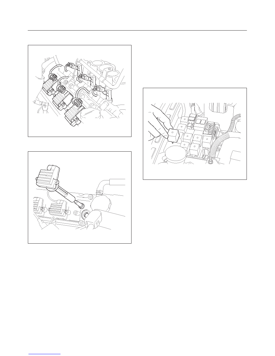
2. Install the coil module and spark plug boot over the

spark plug.

014RW108

3. Secure the coil module to the rocker cover with two

screws.

014RW091

4. Connect the electrical connector at the coil module.
5. Connect the negative battery cable.

Catalytic Converter

Removal and Installation Procedure

Refer to 

Engine Exhaust in Engine.

Air Conditioning Relay

Removal Procedure

1. Remove the fuse and relay box cover from under the

hood.

2. Consult the diagram on the cover to determine which

is the correct relay.

3. Pull the relay straight up and out of the fuse and relay

box.

014RW090

Installation Procedure

1. Insert the relay into the correct place in the fuse and

relay box with the catch slot facing forward.

2. Press down until the catch engages.

f

An audible “click” will be heard.

3. Install the fuse and relay box cover.

EVAP Canister Hoses

Service Information

To view the routing of the EVAP canister hoses, refer to
Vehicle Emission Control Information in Diagnosis.  Use
6148M or equivalent when you replace the EVAP canister
hoses.

6E2–480

RODEO 6VD1 3.2L ENGINE DRIVEABILITY AND EMISSIONS

EVAP Canister

Removal Procedure

1. Disconnect the negative battery cable.
2. Disconnect the two hoses from the EVAP canister.

014RW117

3. Disconnect the fuel vapor connector and the purge

hose from the EVAP canister vent solenoid.

014RW130

4. Remove the two retaining bolts the EVAP canister to

the mounting bracket on the cross member.

014RW131

5. Remove the retaining bolt on the mounting bracket

the slide the canister out of mounting bracket.

014RW129

Inspection Procedure

1. Inspect the hoses for cracks and leaks.
2. Inspect the canister for a damaged case.

6E2–481

RODEO 6VD1 3.2L ENGINE DRIVEABILITY AND EMISSIONS

Installation Procedure

1. Slide the canister into mounting bracket the install the

mounting bracket bolt.

014RW129

2. Install the retaining bolts the EVAP canister to the

mounting bracket on the cross member.

014RW131

3. Connect the fuel vapor connector to the EVAP

canister vent solenoid.

4. Connect the two hoses to the EVAP canister.

014RW130

5. Disconnect the negative battery cable.

EVAP Canister Vent Solenoid

Removal Procedure

1. Disconnect the negative battery cable.
2. Disconnect the connector and hose.

014RW132

6E2–482

RODEO 6VD1 3.2L ENGINE DRIVEABILITY AND EMISSIONS

3. Slide the out of EVAP canister vent solenoid from

mounting bracket.

014RW135

Inspection Procedure

1. Check for cracks or leaks.
2. Energize the solenoid and try to blow through it.  The

solenoid should not allow passage of air when
energized.  (J 35616 Connector Test Kit can be used
to easily attach jumper wires from the battery to the
solenoid).

Installation Procedure

1. Slide the into EVAP canister vent solenoid from

mounting bracket.

014RW135

2. Connect the connector and hose.

014RW132

3. Connect the negative battery cable.

Fuel Tank Pressure Sensor

Removal Procedure

1. Remove the fuel pump assembly.  Refer to 

Fuel Tank

In Fuel Pump.

2. Carefully pry the fuel tank pressure sensor out of the

top of the fuel pump assembly.

014RW133

Inspection Procedure

1. Inspect the vapor pressure sensor for cracks in the

housing and corrosion on the electrical terminals.

2. Inspect the rubber grommet for tears and signs of rot.


Content   ..  429  430  431  432   ..