Isuzu Rodeo UE. Manual - part 411
6E2–399
RODEO 6VD1 3.2L ENGINE DRIVEABILITY AND EMISSIONS
Diagnostic Trouble Code (DTC) P1404 EGR Stuck Closed
D06RW055
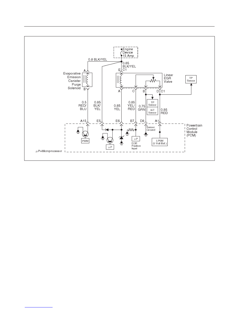
Circuit Description
The powertrain control module (PCM) monitors the EGR
valve pintle position input to ensure that the valve
responds properly to commands from the PCM, and to
detect a fault if current pintle zero position is different from
the learned zero position. If the PCM detects a pintle
position signal indicates more than 30 % different
between current zero position and the learned zero
position for more than 5 seconds, and this condition exists
3 times during trip, then the PCM will set DTC P1404.
Conditions for Setting the DTC
f
Ignition voltage is between 11 and 16 volts.
f
Intake Air temp is more than 3
°
C.
f
Desired EGR position is 0.
f
Difference of EGR pintle position between current and
the learned zero is more than 30 % for more than 5
seconds, and exists three time to the above condition
during a trip the PCM will set DTC 1404. Then it trigger
the PCM lights on.
Action Taken When the DTC Sets
f
The PCM will illuminate the malfunction indicator lamp
(MIL) after consecutive 2nd trip in which the fault is
detected.
f
The PCM will store conditions which were present
when the DTC was set as Freeze Frame and in Failure
Records data.
Conditions for Clearing the MIL/DTC
f
The PCM will turn the MIL “OFF” on the third
consecutive trip cycle during which the diagnostic has
been run and the fault condition is no longer present.
f
A history DTC P1404 will clear after 40 consecutive
warm-up cycles have occurred without a fault.
f
DTC P1404 can be cleared by using the Tech 2 “Clear
Info” function or by disconnecting the PCM battery
feed.
Diagnostic Aids
Check for the following conditions:
f
Excessive carbon deposit on EGR valve shaft and/or
foreign material may cause the EGR valve not to fully
seated. The carbon deposit may occur by unusual port
operation. Remove foreign material and/or excessive
carbon deposit on EGR valve shaft may allow the EGR
valve to be fully seated.
f
Poor connection or damaged harness – Inspect the
wiring harness for damage.
Reviewing the Failure Records vehicle mileage since the
diagnostic test last failed may help determine how often
the condition that caused the DTC to be set occurs. This
may assist in diagnosing the condition.