Isuzu Rodeo UE. Manual - part 350


  Index      Isuzu     Isuzu Rodeo UE - service repair manual 1999 year


Search            


Content   ..  348  349  350  351   ..


Isuzu Rodeo UE. Manual - part 350


6E2–155

RODEO 6VD1 3.2L ENGINE DRIVEABILITY AND EMISSIONS

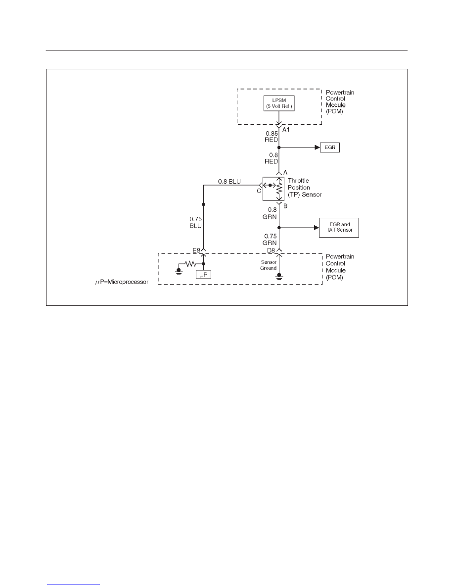
Diagnostic Trouble Code (DTC) P0123 TP Sensor Circuit  High Voltage

D06RW059

Circuit Description

The throttle position (TP) sensor circuit provides a voltage
signal that changes relative to throttle blade angle.  The
signal voltage will vary from about 0.6 volts at closed
throttle to about 4.5 volts at wide open throttle (WOT).
The TP signal is one of the most important inputs used by
the powertrain control module (PCM) for fuel control and
many of the PCM-controlled outputs.

Conditions for Setting the DTC

f

The ignition is “ON.”

f

TP sensor signal voltage is greater than 4.88 volts for
a total of 0.78 second over a 1.5-second period.

Action Taken When the DTC Sets

f

The PCM will illuminate the malfunction indicator lamp
(MIL) the first time the fault is detected.

f

The PCM will store conditions which were present
when the DTC was set as Freeze Frame and in the
Failure Records data.

f

The PCM will use a default throttle position based on
mass air flow and RPM.

Conditions for Clearing the MIL/DTC

f

The PCM will turn the MIL “OFF” on the third
consecutive trip cycle during which the diagnostic has
been run and the fault condition is no longer present.

f

A history DTC P0123 will clear after 40 consecutive
warm-up cycles have occurred without a fault.

f

DTC P0123 can be cleared by using the Tech 2 “Clear
Info” function or by disconnecting the PCM battery
feed.

Diagnostic Aids

Check for the following conditions:

f

The TP sensor shares a 5 Volt Reference with the EGR
Position sensor. Check the 5 Volt reference if these
DTCs are also set.

f

The TP sensor shares a ground with the IAT sensor
and the EGR position Sensor. Check the ground if
these other DTCs are also set.

f

Poor connection at PCM – Inspect harness connectors
for backed-out terminals, improper mating, broken
locks, improperly formed or damaged terminals, and
poor terminal-to-wire connection.

f

Damaged harness – Inspect the wiring harness for
damage.  If the harness appears to be OK, observe the
TP sensor display on the Tech 2 while moving
connectors and wiring harnesses related to the TP
sensor.  A change in the display will indicate the
location of the fault.

f

Faulty TP sensor – With the ignition key “ON,” engine
“OFF,” observe the TP sensor display on the Tech 2
while slowly depressing the accelerator to wide open
throttle.  If a voltage over 4.88 volts is seen at any point
in normal accelerator travel, replace the TP sensor.

If DTC P0123 cannot be duplicated, the information
included in the Failure Records data can be useful in
determining vehicle mileage since the DTC was last set.
If it is determined that the DTC occurs intermittently,

6E2–156

RODEO 6VD1 3.2L ENGINE DRIVEABILITY AND EMISSIONS

performing the DTC P1121 Diagnostic Chart may isolate
the cause of the fault.

Test Description

Number (s) below refer to the step number(s) on the
Diagnostic Chart.
7. Components that share the TP sensor 5 volt reference
“A” circuit include the following device:

f

EGR valve

Disconnect the component while observing the TP
sensor display on the Tech 2.  If the reading
changes drastically when this component is
disconnected, replace the component that
affected the reading.

DTC P0123 – TP Sensor Circuit High Voltage


Step

Action

Value(s)

Yes

No

1

Was the “On-Board Diagnostic (OBD) System Check”
performed?

Go to 

Step 2

Go to 

OBD

System

Check

2

1. Ignition “ON,” engine “OFF.”
2. With the throttle closed, observe the “TP Sensor”

display on the Tech 2.

Is the “TP Sensor” above the specified value?

4.88 V

Go to 

Step 4

Go to 

Step 3

3

1. Ignition “ON,” engine “OFF.”
2. Review and record Tech 2 Failure Records data.
3. Operate the vehicle within Failure Records

conditions as noted.

4. Using a Tech 2, monitor “DTC” info for DTC P0123.

Does the Tech 2 indicate DTC P0123 failed.

Go to 

Step 4

Refer to

Diagnostic

Aids

4

1. Disconnect the TP sensor electrical connector.
2. Observe the “TP Sensor” display on the Tech 2.(If

no, start with diagnostic chart other sensors in the
circuit and see if 5 V returns)

Is the “TP Sensor” near the specified value?

0 V

Go to 

Step 5

Go to 

Step 6

5

Probe the sensor ground circuit at the TP sensor
harness connector with a test light connected to B+.

Is the test light “ON?”

Go to 

Step 7

Go to 

Step 10

6

1. Ignition “OFF,” disconnect the PCM.
2. Ignition “ON,” engine “OFF.”
3. Check for a short to voltage on the TP sensor signal

circuit.

4. If the TP sensor signal circuit is shorted, repair it as

necessary.

Was the TP sensor signal circuit shorted?

Verify repair

Go to 

Step 12

7

1. Ignition “ON.”
2. Monitor the “TP Sensor” Tech 2 display while

disconnecting each of the components that share
the 5 volt reference “A” circuit (one at a time).

3. If the “TP Sensor” Tech 2 display changes, replace

the component that caused the display to change
when disconnected.

Does disconnecting any of these components cause
the “TP Sensor” display to change?

Verify repair

Go to 

Step 8

6E2–157

RODEO 6VD1 3.2L ENGINE DRIVEABILITY AND EMISSIONS

DTC P0123 – TP Sensor Circuit High Voltage

  (Cont'd)

Step

No

Yes

Value(s)

Action

8

1. Ignition “OFF,” disconnect the PCM.
2. Ignition “ON,” engine “OFF.”
3. Check for a short to B+ on the 5 volt reference “A”

circuit.

4. If the 5 volt reference “A” circuit is shorted, repair it

as necessary.

Was the 5 volt reference “A” circuit shorted?

Verify repair

Go to 

Step 9

9

Check for poor electrical connections at the TP sensor
and replace terminals if necessary.

Did any terminals require replacement?

Verify repair

Go to 

Step 11

10

1. Ignition “OFF.”
2. Disconnect the PCM, and check for an open sensor

ground circuit to the TP sensor.

3. If a problem is found, repair it as necessary.

Was the sensor ground circuit to the TP sensor open?

Verify repair

Go to 

Step 12

11

Replace the TP sensor.

Is the action complete?

Verify repair

12

Replace the PCM.

IMPORTANT: The replacement PCM must be
programmed. Refer to 

On-Vehicle Service in

Powertrain Control Module and Sensors for
procedures.

And also refer to latest service bulletin.

Check to see if the Latest software is released or not.
And then Down Load the LATEST PROGRAMMED
SOFTWARE to the replacement PCM.

Is the action complete?

Verify repair

6E2–158

RODEO 6VD1 3.2L ENGINE DRIVEABILITY AND EMISSIONS

Diagnostic Trouble Code (DTC) P0125 ECT Excessive Time to Closed Loop

Fuel Control

D06RW058

Circuit Description

To provide the best possible combination of driveability,
fuel economy, and emission control, a “closed loop”
air/fuel metering system is used.  When the vehicle is first
started, the powertrain control module (PCM) controls
fuel delivery in “open loop,” ignoring the heated oxygen
sensor (HO2S) signals and calculating air/fuel ratio based
on inputs from the engine coolant temperature, throttle
position, and mass air flow sensors.  The PCM will begin
using the Bank 1 HO2S 1 and Bank 2 HO2S 1 signals for
controlling fuel delivery under “closed loop” conditions
when the following conditions have been met:

f

The HO2S output signals are varying, indicating that
the sensors are hot enough to operate properly.

f

The engine coolant temperature sensor indicates
coolant temperature above 50

°

C (122

°

F).

f

Time since start-up is at least 16 seconds for a warm
engine or 23 seconds for a cold engine.

Conditions for Setting the DTC

f

No active IAT or ECT DTC(s)  are present.

f

Engine is running.

f

Vehicle speed is greater than 5 mph (8 km/h) .

f

Intake air temperature is greater than –10

°

C (14

°

F)

0

°

C (32

°

F).

f

Start-up engine coolant temperature is between –10

°

C

(–14

°

F) and 28

°

C (82

°

F).

f

For a warm engine (intake air temperature is greater
than 10

°

C/50

°

F), engine coolant temperature

sufficient to allow “closed loop” operation
(50

°

C/122

°

F) is not achieved within 2 minutes of

start-up.  For a cold engine (intake air temperature
between(–7

°

C and 10

°

C), engine coolant temperature

sufficient to allow “closed loop” operation
(50

°

C/122

°

F) is not achieved within 10 minutes of

start-up.

f

The above condition fails 20 consecutive times.

Action Taken When the DTC Sets

f

The PCM will illuminate the malfunction indicator lamp
(MIL) after the second consecutive trip in which the
fault is detected.

f

The PCM will store conditions which were present
when the DTC was set as Freeze Frame and in the
Failure Records data.

Conditions for Clearing the MIL/DTC

f

The PCM will turn the MIL “OFF” on the third
consecutive trip cycle during which the diagnostic has
been run and the fault condition is no longer present.

f

A history DTC P0125 will clear after 40 consecutive
warm-up cycles have occurred without a fault.

f

DTC P0125 can be cleared by using the Tech 2 “Clear
Info” function or by disconnecting the PCM battery
feed.


Content   ..  348  349  350  351   ..