Isuzu Rodeo UE. Manual - part 264


  Index      Isuzu     Isuzu Rodeo UE - service repair manual 1999 year


Search            


Content   ..  262  263  264  265   ..


Isuzu Rodeo UE. Manual - part 264


6E1–427

RODEO X22SE 2.2L ENGINE DRIVEABILITY AND EMISSION

lower oxygen sensor response. This may cause incorrect
catalyst monitor diagnostic results.
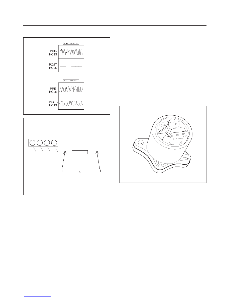
TS24067

D06RX025

Legend

(1) Bank 1 Sensor 1 (Fuel Control)
(2) Catalytic Converter
(3) Bank 1 Sensor 2 (Catalyst Monitor)

Intake Air Temperature (IAT) Sensor

The intake air temperature (IAT) sensor is a thermistor
which changes its resistance based on the temperature of
air entering the engine. Low temperature produces a high
resistance of about 100,000 

W

 at –40

°

C (–104

°

F). High

temperature causes low resistance of about 70 

W

 at

130

°

C (266

°

F). The PCM supplies a 5–volt signal to the

sensor through a resistor internal to the PCM, and then
monitors the signal voltage. The voltage will be high when
the incoming air is cold. The voltage will be low when the
incoming air is hot. By measuring the voltage, the PCM
calculates the incoming air temperature. The IAT sensor
signal is used to adjust spark timing according to the
incoming air density.

The Tech 2 displays the temperature of the air entering
the engine. The temperature should read close to the
ambient air temperature when the engine is cold and rise
as underhood temperature increases. If the engine has
not been run for several hours (overnight), the IAT sensor
temperature and engine coolant temperature should read
close to each other. A failure in the IAT sensor circuit will
set DTC P0112, DTC P1111, DTC P1112,  or DTC P0113.

Linear Exhaust Gas Recirculation (EGR)
Control

The PCM monitors the exhaust gas recirculation (EGR)
actual position and adjusts the pintle position accordingly.
The PCM uses information from the following sensors to
control the pintle position:

f

Engine coolant temperature (ECT) sensor.

f

Throttle position (TP) sensor.

f

Manifold Absolute Pressure (MAP) sensor.

0017

Manifold Absolute Pressure (MAP) Sensor

The manifold absolute pressure (MAP) sensor responds
to changes in intake manifold pressure (vacuum). The
MAP sensor signal voltage to the PCM varies from below
2 volts at idle (high vacuum) to above 4 volts with the
ignition ON, engine not running or at wide–open throttle
(low vacuum).
The MAP sensor is used to determine the following:

f

Manifold pressure changes while the linear EGR flow
test diagnostic is being run. Refer to DTC P0401.

f

Engine vacuum level for other diagnostics.

f

Barometric pressure (BARO).

If the PCM detects a voltage that is lower than the
possible range of the MAP sensor, DTC P0107 will be set.
A signal voltage higher than the possible range of the
sensor will set DTC P0108. An intermittent low or  high
voltage will set DTC P1107 or P1106, respectively. The
PCM can detect a shifted MAP sensor. The PCM
compares the MAP sensor signal to a calculated MAP
based on throttle position and various engine load factors.
If the PCM detects a MAP signal that varies excessively
above or below the calculated value, DTC P0106 will set.

6E1–428

RODEO X22SE 2.2L ENGINE DRIVEABILITY AND EMISSION

014RX013

Powertrain Control Module (PCM)

The powertrain control module (PCM) is located in the
passenger compartment below the center console. The
PCM controls the following:

f

Fuel metering system.

f

Ignition timing.

f

On–board diagnostics for powertrain functions.

The PCM constantly observes the information from
various sensors. The PCM controls the systems that
affect vehicle performance. The PCM performs the
diagnostic function of the system. It can recognize
operational problems, alert the driver through the Check
Engine lamp, and store diagnostic trouble codes (DTCs).
DTCs identify the problem areas to aid the technician in
making repairs.

014RX002

PCM Function

The PCM supplies either 5 or 12 volts to power various
sensors or switches. The power is supplied through
resistors in the PCM which are so high in value that a test
light will not light when connected to the circuit. In some

cases, even an ordinary shop voltmeter will not give an
accurate reading because its resistance is too low.
Therefore, a digital voltmeter with at least 10 meg

W

 input

impedance is required to ensure accurate voltage
readings. Tool J 39200 meets this requirement.
The PCM controls output circuits such as the injectors,
IAC, cooling fan relays, etc., by controlling the ground or
the power feed circuit through transistors or through
either of the following two devices:

f

Output Driver Module (ODM)

f

Quad Driver Module (QDM)

PCM Components

The PCM is designed to maintain exhaust emission levels
to government mandated standards while providing
excellent driveability and fuel efficiency. The PCM
monitors numerous engine and vehicle functions via
electronic sensors such as the throttle position (TP)
sensor, heated oxygen sensor (HO2S), and vehicle
speed sensor (VSS). The PCM also controls certain
engine operations through the following:

f

Fuel injector control

f

Ignition control module

f

Evaporative emission (EVAP) purge

f

A/C clutch control

PCM Voltage Description

The PCM supplies a buffered voltage to various switches
and sensors. It can do this because resistors in the PCM
which are so high in value that a test light may not
illuminate when connected to the circuit. An ordinary shop
voltmeter may not give an accurate reading because the
voltmeter input impedance is too low. Use a 10–megohm
input impedance digital voltmeter (such as J 39200) to
assure accurate voltage readings.
The input/output devices in the PCM include
analog–to–digital converters, signal buffers, counters,
and special drivers. The PCM controls most components
with electronic switches which complete a ground circuit
when turned ON. These switches are arranged in groups
of 4 and 7, called either a quad driver module (QDM),
which can independently control up to 4 output terminals,
or Output Driver Module (ODM) which can independently
control up to 7 outputs. Not all outputs are always used.

PCM Inputs/Outputs

Inputs – Operating Conditions Read

f

Air Conditioning Compressor Clutch ON or OFF

f

Engine Coolant Temperature

f

Crankshaft Position

f

Exhaust Oxygen Content

f

Manifold Absolute Pressure

f

Battery Voltage

f

Throttle Position

f

Fuel Tank Vapor Pressure

f

Fuel Tank Level

f

Exhaust Gas Recirculation (EGR) Feedback

f

Knock

6E1–429

RODEO X22SE 2.2L ENGINE DRIVEABILITY AND EMISSION

f

Vehicle Speed

f

Fuel Pump Voltage

f

Power Steering Pressure

f

Intake Air Temperature

f

Camshaft Position

Outputs – Systems Controlled

f

EVAP Canister Purge Solenoid

f

Exhaust Gas Recirculation (EGR)

f

Ignition Control

f

Fuel Injector Control

f

Idle Air Control

f

Coolant Fan Relays

f

Electric Fuel Pump Relay Compressor Clutch Relay

f

Air Conditioning

f

Diagnostics
– OBD II Malfunction Indicator Lamp (Check Engine

lamp)

– Data Link Connector (DLC)
– Data Output

f

Tachometer Signal

PCM Service Precautions

The PCM is designed to withstand normal current draws
associated with vehicle operation. Avoid over loading any
circuit. When testing for opens and shorts, do not ground
or apply voltage to any of the PCM’s circuits unless
instructed to do so. These circuits should only be tested
using digital voltmeter J 39200. The PCM should remain
connected to the PCM or to a recommended breakout
box.

014RX002

Reprogramming the PCM

The Rodeo allows reprogramming of the PCM without
removing it from the vehicle. This provides a flexible and
cost–effective method of making changes in software
calibrations.

Refer to the latest Isuzu Technical Communication
System information for reprogramming or flashing
procedures.

Tooth Error Correction (TEC) Service Bay
Guidelines

Deceleration Fuel Cut–Off
This procedure is very convenient because it can be done
in the service bay.

CAUTION: Appropriate safety measures should be
taken to assure the safest conditions possible for all
those people in the nearby vicinity of where the tooth
error learn procedure is being performed.

Vehicle Preparation Requirements and Safety Issues
The vehicle needs sufficient engine oil, automatic
transmission fluid, manual transmission gear box oil,
power steering fluid, coolant, and brake fluid. Engine
noise and exhaust should be considered by each
assembly plant when deciding the location to perform the
tooth error learn. Proper safety precautions should be
taken. Anticipate unusual events such as a manual
transmission accidentally being bumped into gear or a
foot slipping off a clutch at high engine speed.  The vehicle
may cause other vehicles to be hit. If the transmission is in
Park during the high engine speeds, the transmission
Park Ratchet experiences excessive vibration and may
momentarily slip. The vehicle is typically then in a Neutral
type state and may roll, especially if the vehicle is on an
incline. Under this condition the transmission should not
slip into gear.
The following summarizes the engine preparation
requirements for a tooth error learn.

Requirements:

1. At least 4 minutes of engine run time is required to

have occurred at lest once during the life of the
vehicle to insure that all of the oil passages are
flushed of debris from machining, casting, and
assembly.

2. At least 5 seconds of engine run time is required

during the same key cycle as the tooth error learn to
fill the oil passages and provide proper lubrication. 10
seconds is the preferred guideline.

3. At least 65 degrees Celsius Coolant temperature.

Engine oil temperature of 38 degrees Celsius is
required for lubrication, which correlates (in most
engines) to 65 degrees Celsius Coolant temperature.
This is a recommendation to insure a sufficiently
lubricated engine 65 degrees Celsius Coolant
temperature correlates to an engine oil temperature
of 38 degrees Celsius.

4. Vehicle must be in Park or Neutral. For a manual

transmission vehicle, the clutch does not need to be
depressed. The tooth error learn may be performed
with either:

1. Gear box in Neutral, it does not matter if the clutch is

depressed or not.

2. Gear Box in a gear and clutch depressed.

NOTE: The first option is the recommended option due to
safety concerns.  The second option has the risk of the

6E1–430

RODEO X22SE 2.2L ENGINE DRIVEABILITY AND EMISSION

operators foot slipping off of the clutch with the vehicle
being revved up and in gear.

5. A/C should always be turned OFF before performing

the TEC learn procedure.

6. A Class II command from the Tech 2 is required to

invoke the TEC learn procedure.

7. No Camshaft and/or Crankshaft Sensor DTC Codes

present.

Tooth Error Learn Procedures
The following steps are required to learn the tooth error
once the above mentioned vehicle preparation
requirements are met:

1. Make sure that the tooth error learn procedure has

been invoked with the Tech 2, other wise when the
throttle is depressed, the RPM would go to the high
RPM fuel cutoff and not be cutoff at the lower tooth
error learning fuel cutoff limit.

2. Depress the brake pedal for safety reasons.
3. Depress the throttle pedal to Wide Open Throttle

(WOT) and keep the throttle at 100% for the duration
of the Tooth Error Correction (TEC) learning process
until the TEC is learned or the number of attempts to
learn has been exceeded. The RPM will be limited to
the upper TEC RPM limit until one of the two above
mentioned conditions are met and the throttle is
released to less than 5% Throttle Position Sensor
(TPS). After this, the RPM limit will be the normal
redline RPM limit.

4. The tooth error learning diagnostic will learn the tooth

error as the engine decelerates in fuel cutoff.

5. During the tooth error learning procedure. TEC

specific information is available which will indicate
that the tooth error was properly learned and
completed.

Considerations For Locating The Tooth Error
Learning Procedure
The area that the tooth error learn is done should be well
ventilated or have vehicle exhaust elimination system
which attaches to the tail pipe and draws the vehicle
exhaust out of the building.

CAUTION: Appropriate safety measures should be
taken to assure the safest conditions possible for all
those people in the nearby vicinity of where the tooth
error learn procedure is being performed. If possible,
anchored or secured safety barriers should be in
place in at least the front of the vehicle and in the
back of the vehicle if possible to reduce the
possibility of accidents. The figure below shows the
proper placement of a frontal safety barrier.
The area that the tooth error learn is done should be
well ventilated or have vehicle exhaust elimination
system which attaches to the tail pipe and draws the
vehicle exhaust out of the building.

Throttle Position (TP) Sensor

The throttle position (TP) sensor is a potentiometer
connected to the throttle shaft on the throttle body. The

PCM monitors the voltage on the signal line and
calculates throttle position. As the throttle valve angle is
changed (accelerator pedal moved), the TP sensor signal
also changes. At a closed throttle position, the output of
the TP sensor is about 0.25 volts. As the throttle valve
opens, the output increases so that at wide open throttle
(WOT), the output voltage should be about 4.75 volts.
The PCM calculates fuel delivery based on throttle valve
angle (driver demand). A broken or loose TP sensor may
cause intermittent bursts of fuel from an injector and
unstable idle because the PCM thinks the throttle is
moving. A hard failure in the TP sensor 5–volt reference
or signal circuits will set either a DTC P0122 or DTC
P0123. A hard failure with the TP sensor ground circuit
may set DTC P0123 and DTC P0122. Once a DTC is set,
the PCM will use an artificial default value based on
engine RPM and mass air flow for the throttle position,
and some vehicle performance will return. A high idle may
result when either DTC P0122 or DTC P0123 is set. The
PCM can detect intermittent TP sensor faults. DTC
P1121 or DTC P1122 will set if an intermittent high or low
circuit failure is being detected.

101RX003

Transmission Range Switch

IMPORTANT:

The vehicle should not be driven with the

transmission range switch disconnected; idle quality will
be affected.
The four inputs from the transmission range switch
indicate to the PCM which position is selected by the
transmission selector lever.  This information is used for
ignition timing, EVAP canister purge, EGR and IAC valve
operation.
For more information on the transmission range switch,
refer to 4L30–E Automatic Transmission.

Vehicle Speed Sensor (VSS)

The PCM determines the speed of the vehicle by
converting a pulsing voltage signal from the vehicle speed


Content   ..  262  263  264  265   ..