Isuzu Rodeo UE. Manual - part 132


  Index      Isuzu     Isuzu Rodeo UE - service repair manual 1999 year


Search            


Content   ..  130  131  132  133   ..


Isuzu Rodeo UE. Manual - part 132


6A–17

ENGINE MECHANICAL (X22SE 2.2L)

Installation

1. Install the camshaft position sensor and tighten

timing rear cover bolt.

Torque: 8 N·m (5.9 lb ft)

020RW012

2. Install the cylinder head cover and tighten bolts to the

specified torque.

Torque: 8 N·m (5.9 lb ft)

3. Install the timing belt front cover then tighten fixing

bolts to the specified torque.

Torque: 6 N·m (4.4 lb ft)

4. Install the crankshaft pulley, tighten fixing bolts to the

specified torque.

Torque: 20 N·m (14 lb ft)

020RW014

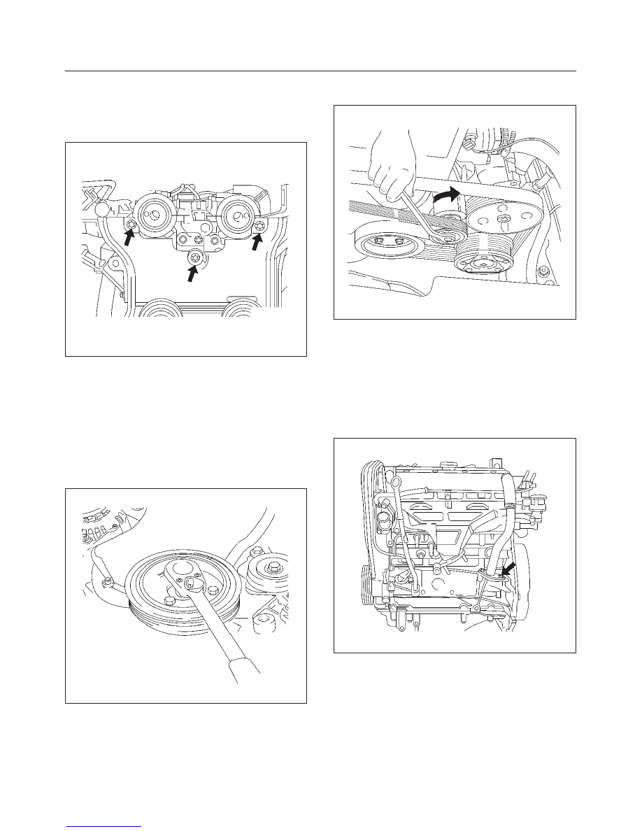
5. Move drive belt tensioner to loose side using wrench

then install the drive belt to normal position.

033RW001

6. Connect ignition cable to ignition plug.
7. Install ignition cable cover to cylinder head cover and

tighten two bolt to the specified torque.

Torque: 3 N·m (2 lb ft)

8. Install intake duct bracket to cylinder block.
9. Install PCV hose flange to cylinder block to the

specified torque.

Torque: 25 N·m (18 lb ft)

020RW015

6A–18

ENGINE MECHANICAL (X22SE 2.2L)

10. Connect cooling fan wire harness connector to

cooling fan  on left side top of fan shroud.

11. Connect left side ground cable to cylinder head cover

and connect other side connector to left side wheel
arch terminal.
Connect right side ground cable to generator stay and
connect other side connector to right side wheel arch
terminal.

12. Connect three(black, green and blue colors) engine

wire harness connector to chassis harness of left rear
side of engine compartment.

13. Install intake duct.
14. Connect PCV hose to cylinder head cover.
15. Connect battery ground cable.

Exhaust Manifold

Removal

1. Disconnect battery ground cable.
2. Disconnect PCV hose from air intake duct.
3. Remove a nut from air intake duct bracket and loosen

hose clamp on throttle body. Remove air intake duct
assembly with air cleaner cover.

4. Remove air intake duct bracket with ground cable.
5. Remove four fixing bolts on exhaust manifold heat

protector.

6. Remove fixing four nuts from flange of front exhaust

pipe and remove fixing bolts from silencer side.

027RW005

7. Remove ten exhaust manifold fixing nuts then

remove exhaust manifold.

Installation

1. Install exhaust manifold and tighten fixing nuts to be

tightened in three steps.

f

Tightening sequence:

f

Step1: J G H B D C J G B D

f

Step2: A B C D E F G H J K

f

Step3: A B C D E F G H J K

f

Tightening torque:

f

Step1: 14 N·m (10 Ib ft)

f

Step2: 20 N·m (14 Ib ft)

f

Step3: 20 N·m (14 Ib ft)

011RW029

2. Install front exhaust pipe to exhaust manifold and

tighten fixing nut to the specified torque.

Torque: 25 N·m (18 lb ft)

027RW005

3. Tighten silencer side bolt to the specified torque.

Torque: 68 N·m (50 lb ft)

4. Install exhaust manifold heat protector and tighten

bolt.

Torque: 8 N·m (5.9 lb ft)

6A–19

ENGINE MECHANICAL (X22SE 2.2L)

5. Install intake duct bracket with ground cable.
6. Install intake duct assembly to throttle body and air

cleaner then tighten nut to the intake duct bracket and
clamp on the throttle body side, also clamp air cleaner
cover.

7. Connect PCV hose to air intake duct.
8. Connect battery ground cable.

Crankshaft Pulley

Removal

1. Disconnect battery ground cable.
2. Move drive belt tensioner to loose side by using

wrench then remove drive belt.

033RW001

3. Remove four crankshaft pulley fixing bolts, remove

crankshaft pulley.

020RW014

Installation

1. Install the crankshaft pulley to crankshaft flange.
2. Tighten four bolt to the specified torque.

Torque: 20 N·m (14 lb ft)

020RW014

3. Move drive belt tensioner to loose side by using

wrench, then install drive belt to normal position.

033RW001

4. Connect battery ground cable.

6A–20

ENGINE MECHANICAL (X22SE 2.2L)

Intake Manifold

Removal

1. Disconnect battery ground cable.
2. Remove PCV hose from air intake duct.
3. Remove a nut from air intake duct bracket and loosen

hose clamp on throttle body. Remove air intake duct
assembly with air cleaner cover.

4. Drain engine coolant.
5. Remove water hoses from throttle body.
6. Disconnect the connector for throttle position sensor,

idle air control valve sensor from throttle body.

7. Remove fuel pipe joint eye bolts from fuel rail and

disconnect wire harness from fuel injector.

042RW001

8. Disconnect hose from fuel pressure regulator then

remove fuel rail assembly.

9. Remove throttle valve control cable from throttle

body.

10. Remove fixing bolts for generator bracket.

065RW025

11. Remove water pipe fixing bolt then remove water

pipe.

12. Remove fixing bolt from bracket (Between cylinder

block and intake manifold) of intake manifold side.

025RW002

13. Remove ignition coil bracket fixing bolt.
14. Remove bolt and seven nuts, and remove intake

manifold.

027RW002


Content   ..  130  131  132  133   ..