Isuzu Rodeo UE. Manual - part 55
4A1–11
DIFFERENTIAL (FRONT)
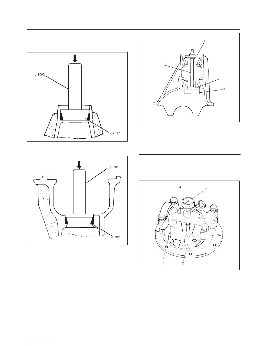
Reassembly
1. Using installer J–7817 and grip J–8092, install outer
bearing outer race.
415RW013
2. Using installer J–7818 and grip J–8092, install Inner
bearing outer race.
415RW014
3. Install adjust shim and adjust drive pinion mounting
distance:
1. Apply gear oil to the inner and outer drive pinion
bearing.
Clean the pinion setting gauge set.
Then install the gauge set together with the inner
and outer bearings.
2. Tighten the nut to the specified torque.
Torque: 2.3 N·m (20 lb in)
425RW030
Legend
(1) Pilot : J–21777–42
(2) Pilot : J–42479–2
(3) Gauge Plate : J–42479–1
(4) Nut and Stud : J–21777–43
3. Clean the side bearing bores. Install the dial
indicator with the discs and arbor. Install and
tighten the bearing caps to the specified torque.
Torque: 97 N·m (72 lb ft)
425RW031
Legend
(1) Dial Indicator: J–8001
(2) Gauge Plate: J–42479–1
(3) Disc (2 pcs.): J–23597–8
(4) Arbor: J–23597–1