Isuzu Rodeo UE. Manual - part 52
WHEEL AND TIRE SYSTEM
3E–13
480RS013
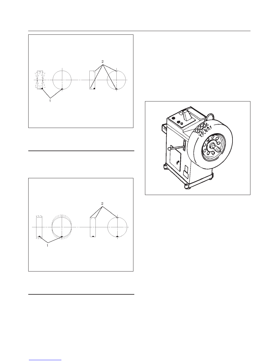
Legend
(1) Heavy Spot Wheel Shimmy
(2) Add Balance Weights Here
Dynamic balance is the equal distribution of weight on
each side of the wheel center-line so that when the tire
spins there is no tendency for the assembly to move from
side to side. Assemblies that are dynamically unbalanced
may cause shimmy.
480RS014
Legend
(1) Heavy Spot Wheel Hop
(2) Add Balance Weights Here
WARNING: STONES SHOULD BE REMOVED FROM
THE TREAD TO AVOID OPERATOR INJURY DURING
SPIN BALANCING AND TO OBTAIN A GOOD
BALANCE.
Balancing Wheel and Tire
On-vehicle Balancing
On-Vehicle balancing methods vary with equipment and
tool manufacturers. Be sure to follow each
manufacturer’s instructions during balancing operation.
Off-vehicle Balancing
Most electronic off-vehicle balancers are more accurate
than the on-vehicle spin balancers. They are easy to use
and give a dynamic balance. Although they do not correct
for drum or disc unbalance (as on- vehicle spin balancing
does), they are very accurate.
480RS015