Isuzu Rodeo UE. Manual - part 15
1A–30 HEATING, VENTILATION AND AIR CONDITIONING (HVAC)
Triple Pressure Switch (V6, A/T)
Triple pressure switch (2) is installed on the upper part of
the receiver/drier. This switch is constructed with a
unitized type of two switches. One of them is a low and
high pressure switch (Dual pressure switch) to switch
“ON” or “OFF” the magnetic clutch as a result of
irregularly high–pressure or low pressure of the
refrigerant. The other one is a medium pressure switch
(Cycling switch) to switch “ON” or “OFF” the condenser
fan sensing the condenser high side pressure.
Compressor
ON
(kPa/psi)
OFF
(kPa/psi)
Low-pressure
control
186.3
±
29.4
(27.0
±
4.3)
176.5
±
24.5
(25.6
±
3.6)
High-pressure
control
2353.6
±
196.1
(341.3
±
28.4)
2942.0
±
196.1
(426.6
±
28.4)
Condenser fan
ON
(kPa/psi)
OFF
(kPa/psi)
Medium-pressure
control
1471.0
±
98.1
(213.3
±
14.2)
1078.7
±
117.7
(156.4
±
17.1)
Pressure Sensor
The pressure sensor (2) is installed on the upper part of
the receiver/drier. This sensor converts high pressure
detection of refrigerant to an electrical voltage signal and
supplies it to the ECM. The ECM controls switching
compressor idle speed and cooling fan operation by the
electrical voltage signal.
875RW007
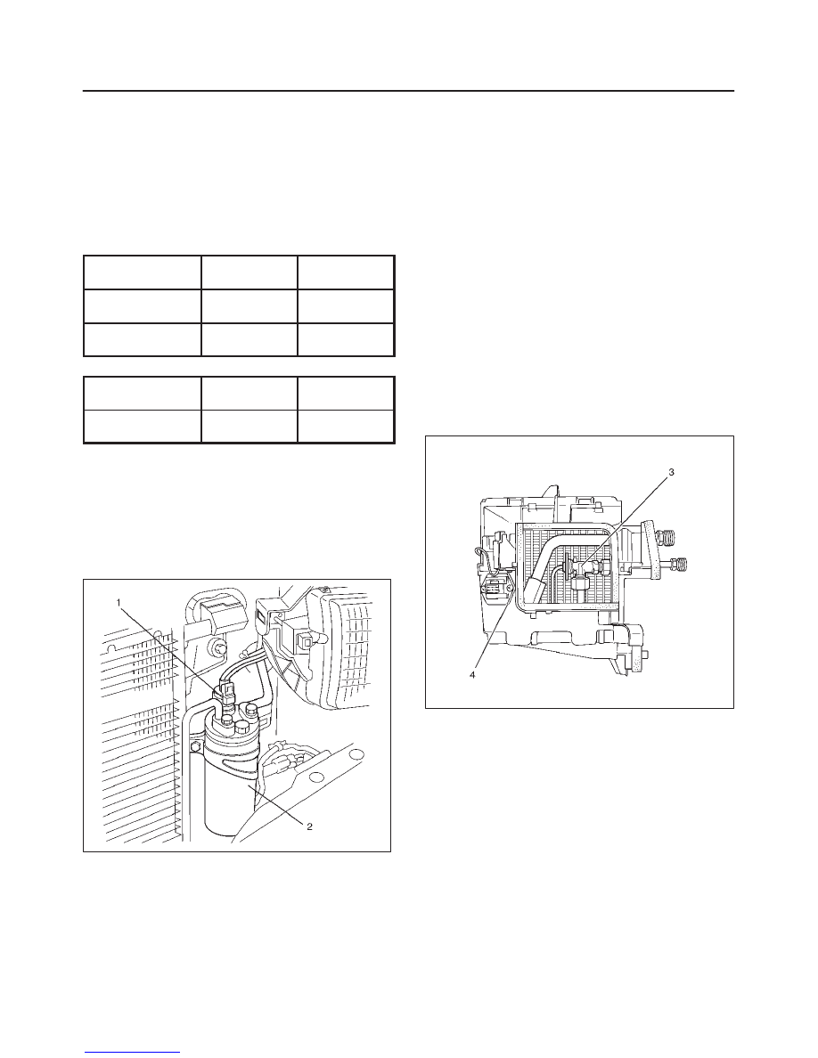
Expansion Valve
This expansion valve (3) is an external pressure type and
it is installed at the evaporator intake port.
The expansion valve converts the high pressure liquid
refrigerant sent from the receiver/drier to a low pressure
liquid refrigerant by forcing it through a tiny port before
sending it to the evaporator (4).
This type of expansion valve consists of a temperature
sensor, diaphragm, ball valve, ball seat, spring
adjustment screw, etc.
The temperature sensor contacts the evaporator outlet
pipe, and converts changes in temperature to pressure. It
then transmits these to the top chamber of the
diaphragm.
The refrigerant pressure is transmitted to the diaphragm’s
bottom chamber through the external equalizing pressure
tube.
The ball valve is connected to the diaphragm. The
opening angle of the expansion valve is determined by
the force acting on the diaphragm and the spring
pressure.
The expansion valve regulates the flow rate of the
refrigerant. Accordingly, when a malfunction occurs to
this expansion valve, both discharge and suction
pressure get low, resulting in insufficient cooling capacity
of the evaporator.
The calibration has been changed to match the
characteristics of HFC-134a.
874RX003
Evaporator
The evaporator cools and dehumidifies the air before the
air enters the passenger compartment. High-pressure
liquid refrigerant flows through the expansion valve (2)
into the low-pressure area of the evaporator. The heat in
the air passing through the evaporator core (1) is lost to
the cooler surface of the core, thereby cooling the air.
As heat is lost between the air and the evaporator core
surface, moisture in the vehicle condenses on the outside
surface of the evaporator core and is drained off as water.
When the evaporator malfunctions, the trouble will show
up as an inadequate supply of cool air. The cause is
typically a partially plugged core due to dirt, or a
malfunctioning blower motor.