Isuzu KB P190. Manual - part 951
Automatic Transmission – 4L60E – Electrical Diagnosis
Page 7C2–18
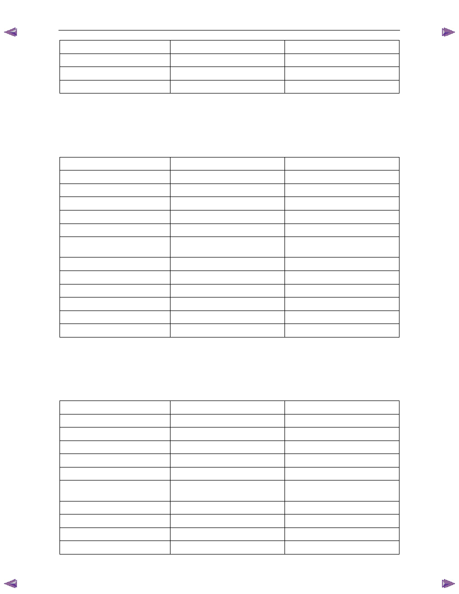
Tech 2 Parameter
Units Displayed
Typical Data Value
Transmission Fluid Temp
°C
Varies
Estimated Gear Ratio
Ratio
8.00:1
Transmission Hot Mode
On / Off
Off
1-2 Shift Data
Once this mode is selected, displays specific parameter information about the 1-2 shift solenoid valve and its circuits.
1-2 Shift Data Parameters
For definitions of the parameters in this table, refer to 3.3
Tech 2 Data Definitions.
Tech 2 Parameter
Units Displayed
Typical Data Value
Shift Solenoid A
On / Off
Varies
Shift Solenoid B
On / Off
Varies
Commanded Gear
1,2,3,4
1
1-2 Shift Time
Seconds
Varies
1-2 Shift Error
Seconds
Varies
Shift Solenoid A Circuit
Open or Shorted / Short to Battery /
Okay
Okay
Throttle Position
Percent
Varies
Engine Speed
RPM
Varies
AT Input Speed
N/A
N/A
AT Output Speed
RPM
Varies
Vehicle Speed
km/h
0
Estimated Gear Ratio
Ratio
8.00:1
2-3 Shift Data
Once this mode is selected, displays specific parameter information about the 2-3 shift solenoid valve and its circuits.
2-3 Shift Data Parameters
For definitions of the parameters in this table, refer to 3.3
Tech 2 Data Definitions.
Tech 2 Parameter
Units Displayed
Typical Data Value
Shift Solenoid A
On / Off
Varies
Shift Solenoid B
On / Off
Varies
Commanded Gear
1,2,3,4
1
2-3 Shift Time
Seconds
Varies
2-3 Shift Error
Seconds
Varies
Shift Solenoid B Circuit
Open or Shorted / Short to Battery /
Okay
Okay
Throttle Position
Percent
Varies
Engine Speed
RPM
Varies
AT Input Speed
N/A
N/A
AT Output Speed
RPM
Varies