Isuzu KB P190. Manual - part 899


  Index      Isuzu     Isuzu KB P190 - service repair manual 2007 year


Search            


Content   ..  897  898  899  900   ..


Isuzu KB P190. Manual - part 899


Charging System – V6 

Page 6D1-1-9 


2.5 

Charging System Inoperative / 
Malfunctioning 

Diagnostic Table Notes 

Reference to following information will assist when diagnosing charging system faults. 

For all wiring harness fault diagnoses, refer to 8A Electrical Body and Chassis. 

For wiring harness repairs, refer to 8A Electrical Body and Chassis. 

Refer to 8A Electrical Body and Chassis for harness routing. 

Ensure the battery, cables and connections are in good order. Refer to 6D1-3 Battery – V6. 

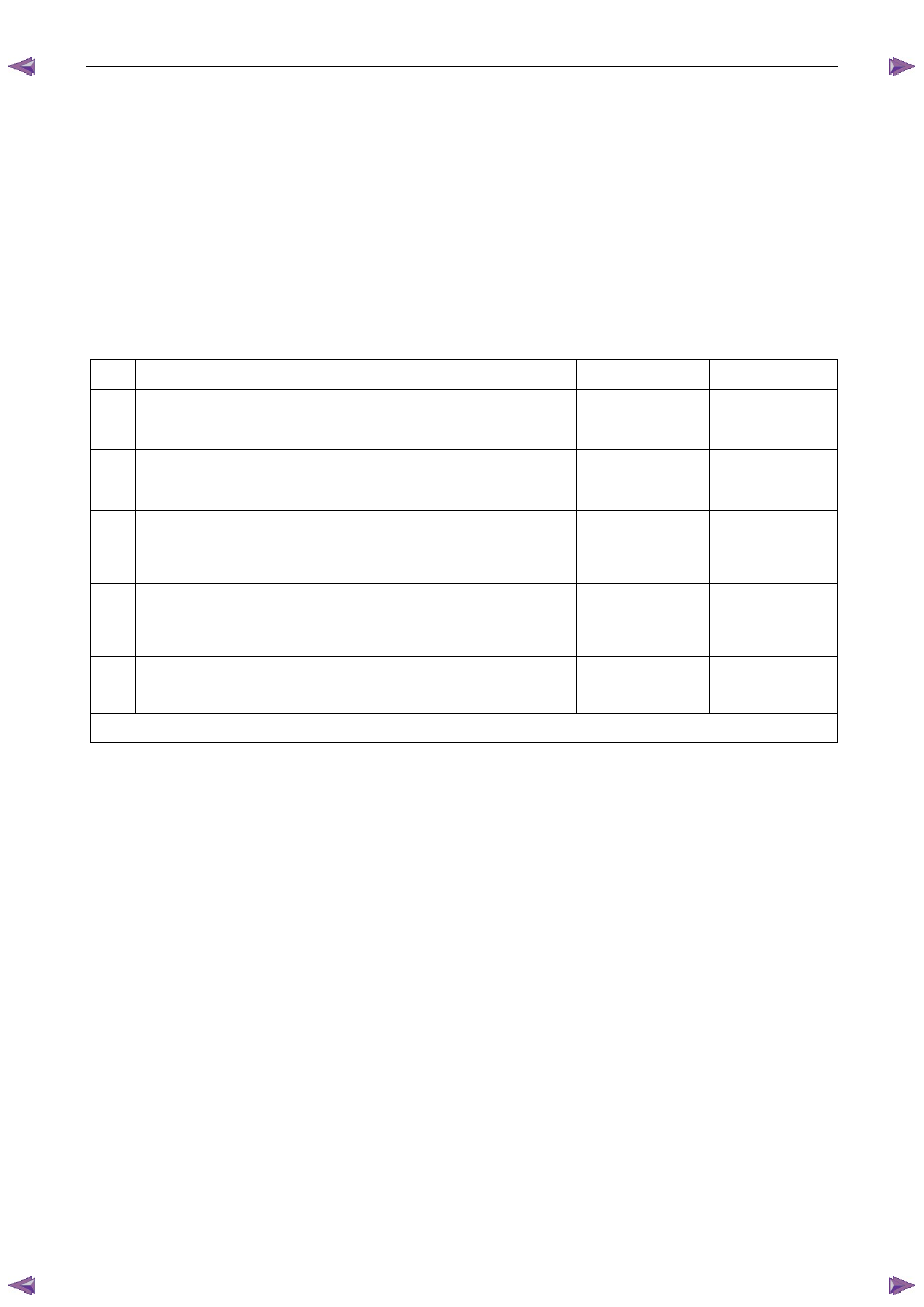
Diagnostic Table 120A Generator 

Step Action 

Yes 

No 

Did you review 1.3 

System Operation? 

Go to Step 2 

Go to 1.3

 System 

Operation 

Did you read 2.3  Diagnostic Systems Check 

Go to Step 3 

Go to 2.3

 Diagnostic 

Systems Check 

Perform the Generator On-vehicle Checks 

Was the generator serviceable? 

Go to step 4 

Replace the 

generator. 

Go to Step 5 

Perform the Charging Circuit Voltage Drop Test. 

Was the wiring serviceable? 

Go to 8A Electrical 

Body and Chassis 

Go to Step 5 

Repair as required 

(refer to Note 2).

Go to Step 5 

Operate the system to verify the repair. 

Did you correct the condition? 

System OK 

Go to Step 2 

When all diagnosis and repairs are completed, check the system for correct operation. 

Charging System – V6 

Page 6D1-1-10 


Minor Service Operations 

3.1 Safety 

Precautions 

Observe the following precautions. Failure to observe these precautions will result in serious damage to the generator. 

• 

Only use the generator and voltage regulator in a negative ground system. 

• 

Always refer to 1.2  WARNING, CAUTION and NOTES before disconnecting the battery. 

• 

When installing a battery, fit the positive (+) cable to the battery before fitting the negative cable. 

• 

When a slave battery is used for starting purposes, ensure that both batteries are connected in parallel. That is, 
positive terminals connected and negative terminals connected. 

• 

Only use jumper leads that have surge protection. 

• 

Disconnect both battery cables when charging the battery. This isolates the generator from the battery and from 
the external charging equipment. 

• 

Do not operate the generator within an open circuit or without a battery in the circuit. 

• 

Do not disconnect the battery while the generator is running. 

• 

Do not attempt to polarise the generator. 

• 

Do not connect generator connector E-4 pin 1 to 12 V (the battery or ignition circuits). 

• 

Some battery powered timing lights can produce high transient voltages when connected or disconnected. 
Only disconnect or connect timing lights when the engine is switched off. 


Ensure the generator connector E-4 pin 1 has 
a maximum sinking current of 50mA. 

3.2 Maintenance 

Regular Checks 

Check the following at regular intervals: 

• 

generator terminals – for corrosion and loose connections, 

• 

wiring – for continuity and damaged insulation, 

• 

mounting bolts – for tightness, 

• 

drive belt – for alignment and wear, and 

• 

drive pulley – for damage and warping. 

NOTE 

The drive-belt adjustment for the engine 
ancillaries (i.e. generator and water pump) is 
provided by a spring-loaded tensioner. Therefore, 
the drive belt does not require manual 
adjustment. 

Lubrication 

High tolerance bearings are used in this generator. If the bearings are removed during the generator disassembly, new 
bearings must be installed to restore the generator to original specification. The ball bearings supporting the rotor shaft 
are pre-lubricated and sealed. Do not attempt to lubricate these during servicing. 

Charging System – V6 

Page 6D1-1-11 


3.3 On-vehicle 

Testing 

Generator On-vehicle Checks 

Prerequisites 

Before testing the generator output, ensure that: 

• 

all generator circuit connections are clean and tight, 

• 

the generator is always connected to the battery during testing (to prevent damage to the diodes), 

• 

the battery is fully charged, and 

• 

the specific gravity does not vary more than 0.025 between cells. (It is recommended the average specific gravity 
is 1.260 or higher). Refer to 6D1-3 Battery – V6. 

Carry out a load test on the battery to determine its ability to supply and accept current. This is a good indicator of the 
general condition of the battery. For details of battery testing, refer to 6D1-3 Battery – V6. 

Inspect the drive belt and tensioner markings to determine if the drive belt is within operating limits. Replace the belt if it 
is excessively worn or outside the operating range of the tensioner. 

For further details, refer to 6A1 Engine Mechanical – V6. 

Generator Test 

Regulating Voltage Test 

N O T E  

Leave the generator E-4 wiring harness 
connector connected, as it provides initial field 
excitation. 

Ensure the ignition switch is in the OFF position and 
all electrical equipment is turned off. 


Refer to 1.2 

WARNING, 

CAUTION 

and 

NOTES before disconnecting the battery. 

Disconnect the battery ground cable P-5 at the 
battery. 

Disconnect the generator positive lead P-9 from the 
generator . Connect the positive lead of a multimeter 
set to measure current (1) to P-9 (2). 

Connect that multimeter’s negative lead to the 
disconnected generator positive lead (3). 

Connect the positive lead of a multimeter set to 
measure voltage (4) to P-9 (5). 

Connect that multimeter’s negative lead to a good 
ground connection on the generator housing (6). 


Insulate the terminal of the generator 
positive lead P-9 to prevent contact with any 
metal part of the vehicle. If the terminal is 
grounded, damage to the charging circuit 
can result when the battery is reconnected. 

Figure 6D1-1 3 

Charging System – V6 

Page 6D1-1-12 


Reconnect the battery ground cable P-5. 

Fit a loading device (7) across the battery terminals, e.g. an adjustable carbon pile. 


The loading device must have a minimum 
power consumption of 1000 W. 

Record the voltage reading before starting the engine. (This reading should increase when the engine is running, 
indicating generator output.). 

10 

Start the engine. 

11 

Increase the engine speed to the value outlined in the chart below. 

12 

Using the reading from the multimeter set to measure current, adjust the loading device to apply a load within the 
range outlined in the chart below. 

13 

Using the multimeter set to measure voltage, check the generator output voltage against the specification.  

Engine RPM ........................................................... 1300 

Load................................................................5.0 – 10 A 

Output Voltage...........................................13.8 – 15.4 V 


Load Regulation Test 

N O T E  

The decrease in the voltage recorded during this 
test should not exceed 0.5 V from the readings 
obtained for the Regulating Voltage Test. If the 
decrease in the regulating voltage is greater than 
0.5 V, the regulator is defective. Replace the 
regulator. 

14 

Increase the engine speed to the value outlined in the chart below. 

15 

Using the reading from the multimeter set to measure current, adjust the loading device to apply a load of about 
90% of the generator’s full output. 

16 

Using the multimeter set to measure voltage, check the generator output voltage against the specification. 

Engine RPM............................................................ 1900 

Load.........................................................................90 A 

Output Voltage...........................................13.8 – 15.4 V 

Full Load Output Test 


Keep the time for this test to a minimum to 
avoid undue heating and high engine speeds. 

17 

Increase the engine speed to the value outlined in the chart below . 

18 

Using the reading from the multimeter set to measure voltage, adjust the loading device to increase the load until 
the generator output voltage drops to 13.5 V. Full generator output, outlined in the chart below, is required. 

19 

Record the current reading displayed on the multimeter set to measure current. 


Content   ..  897  898  899  900   ..