Isuzu KB P190. Manual - part 861


  Index      Isuzu     Isuzu KB P190 - service repair manual 2007 year


Search            


Content   ..  859  860  861  862   ..


Isuzu KB P190. Manual - part 861


Engine Management – V6 – Diagnostics 

Page 6C1-2–166 


Test Description 

The following numbers refer to the step numbers in the diagnostic table: 

This step tests the ECM ground circuits and supply voltage. 

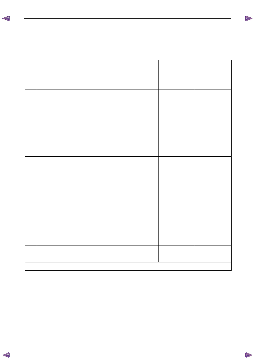
DTC P1648 Diagnostic Table 

Step Action 

Yes 

No 

Has the Diagnostic System Check been performed? 

Go to Step 2 

Refer to 

4.4 Diagnostic 
System Check in 

this Section 

Switch off the ignition for 30 seconds. 

Using Tech 2, select the DTC display function. 

N O T E  

Do not attempt to perform any Tech 2 function that 
requires the ECM security code to be entered. 

Does DTC P1648 fail this ignition cycle? 

Go to Step 4 

Go to Step 3 

Using Tech 2, attempt a programming function that requires the ECM 
security code to be entered. Refer to 6C1-3 Engine Management –V6 
– Service Operations for details on resetting the ECM. 

Has the programming function been successfully performed? 

System OK  

Go to Step 4 

Test all ECM ground circuits for a high resistance or an open 
circuit fault condition. Refer to 8A Electrical - Body and Chassis 
for information on electrical fault diagnosis. 

Test the ECM ignition supply voltage circuit for a high 
resistance, open circuit or short to ground fault condition. Refer 
to 8A Electrical - Body and Chassis for information on electrical 
fault diagnosis. 

Has any fault been found and rectified? 

Go to Step 6 

Go to Step 5 

Replace the ECM. Refer to 6C1-3 Engine Management –V6 – Service 
Operations for details on replacing the ECM. 

Has the repair been completed? 

Go to Step 6 

 — 

Using Tech 2, clear the DTCs. 

Switch off the ignition for 30 seconds. 

Does DTC P1648 fail this ignition cycle? 

Go to Step 2 

Go to Step 7 

Using Tech 2, select the DTC display function. 

Does Tech 2 display any DTCs? 

Go to the 

appropriate DTC 

Table in this Section 

System OK 

When all diagnosis and repairs are completed, clear all DTCs and check the system for correct operation. 

7.44  DTC P1668, P2500 or P2501 

DTC Descriptors 

This diagnostic procedure supports the following DTCs: 

• 

DTC P1668 – Generator L Terminal Circuit Malfunction 

• 

DTC P2500 – Generator L Terminal Low Voltage 

• 

DTC P2501 – Generator L Terminal High Voltage 

Engine Management – V6 – Diagnostics 

Page 6C1-2–167 


Circuit Description 

The engine control module (ECM) applies a signal voltage to the Generator L (GEN L) terminal circuit to control the load 
of the generator on the engine. Refer to 6D1-1 Charging System for details of the charging system operation.  

A GEN L terminal circuit DTC sets if the ECM detects the Gen L circuit voltage is outside the specified range for a 
predetermined set of parameters. 

Conditions for Running the DTC 

DTC P1668 

Runs continuously when one of the following conditions are met: 

• 

Ignition on Test – The ignition is switched on with the engine not running for 5 seconds. 

• 

Engine Run Test – The engine is running at speed less than 3,000 rpm 

DTC P2500 

Runs continuously when the following conditions are met: 

• 

There is no generator, CKP sensor or CMP sensor DTC set. 

• 

The engine is running. 

• 

The generator is not commanded off. 

DTC P2501 

Runs continuously when the following conditions are met: 

• 

There is no generator, CKP sensor or CMP sensor DTC set. 

• 

The ignition is switched on with the engine not running. 

Conditions for Setting the DTC 

DTC P1668 

• 

Ignition on Test – the ECM detects a high signal voltage on the Gen L for 5 seconds. 

• 

Engine Run Test – the ECM detects a low signal voltage on the Gen L for 5 seconds. 

DTC P2500 

The ECM detects a low signal voltage on the Gen L for 15 seconds. 

DTC P2501 

The ECM detects a high signal voltage on the Gen L for 5 seconds. 

Conditions for Clearing DTC 

The Generator L-terminal circuit are Type C DTCs. Refer to 1.4  Diagnostic Trouble Codes in this Section, for action 
taken when a Type C DTC sets and conditions for clearing Type C DTCs. 

Additional Information 

• 

For an intermittent fault condition, refer to 5.2 

Intermittent Fault Conditions in this Section. 

• 

Refer to 6C1-1 Engine Management – V6 – General Information for details of the ECM operation. 

• 

Refer to 6D1-1 Charging System – V6 for details of the charging system operation. 

• 

Since fault condition in a wiring connector may trigger DTCs, always test the connectors related to this diagnostic 
procedure for shorted terminals or poor wiring connection before replacing any component. Refer to 8A Electrical - 
Body and Chassis for information on electrical fault diagnosis. 

Engine Management – V6 – Diagnostics 

Page 6C1-2–168 


• 

To assist diagnosis, refer to 3 

Wiring Diagrams and Connector Charts in this Section, for the system wiring 

diagram and connector charts. 

DTC P1668, P2500 or P2501 Diagnostic Table 

Step Action 

Yes 

No 

Has the Diagnostic System Check been performed? 

Go to Step 2 

Refer to 

4.4 Diagnostic 

System Check in 

this Section 

Switch off the ignition for 30 seconds. 

Operate the vehicle within the conditions for running the DTC. 

Using Tech 2, select the DTC display function. 

Does DTC P1668, P2500 or P2501 fail this ignition cycle? 

Go to Step 3 

Refer to Additional 

Information in this 

DTC 

Test the charging system for any fault condition that may cause 
incorrect generator operation. Refer to 6D1-1 Charging System – V6.

Was any fault found and rectified? 

Go to Step 6 

Go to Step 4 

Test the Gen L signal circuit for a high resistance, open circuit, short 
to ground or short to voltage fault condition. Refer to 8A Electrical - 
Body and Chassis for information on electrical fault diagnosis. 

Was any fault found and rectified? 

Go to Step 6 

Go to Step 5 

Replace the ECM. Refer to 6C1-3 Engine Management – V6 – 
Service Operations. 

Was the repair completed? 

Go to Step 6 

— 

Using Tech 2, clear the DTCs. 

Switch off the ignition for 30 seconds. 

Start the engine. 

Operate the vehicle within the conditions for running the DTC. 

Does any of the Generator L terminal circuit DTCs fail this ignition 
cycle? 

Go to Step 2 

Go to Step 7 

Using Tech 2, select the DTC display function. 

Does Tech 2 display any DTCs? 

Go to the 

appropriate DTC 

Table in this Section 

System OK 

When all diagnosis and repairs are completed, check the system for correct operation. 

7.45 DTC 

P1845 

DTC Descriptor 

This diagnostic procedure supports DTC P1845 – Engine Torque Reduction Malfunction 

Circuit Description 

The ECM monitors and compares the engine torque output against the maximum allowable engine torque. Refer to  
6C1-1 Engine Management – V6 – General Information for details of the engine torque limit management operation. 

If the requested torque is higher than the maximum allowable torque, the ECM applies engine torque limitation and DTC 
P1845 – Engine Torque Reduction Malfunction sets. 

Conditions for Running the DTC 

DTC P1845 runs continuously when the engine is running at speeds greater than 40 rpm. 

Engine Management – V6 – Diagnostics 

Page 6C1-2–169 


Conditions for Setting the DTC 

The engine torque output exceeds the maximum allowable torque output for 10 minutes. 

Conditions for Clearing the DTC 

DTC P1845 – Engine Torque Reduction Malfunction is a Type ‘C’ DTC. Refer to 1.4 

Diagnostic Trouble Codes in this 

Section, for action taken when a Type ‘C’ DTC sets and conditions for clearing Type ‘C’ DTC. 

Additional Information 

• 

Refer to 6C1-1 Engine Management – V6 – General Information for details of the Engine Torque Limit 
Management operation. 

• 

For an intermittent fault condition, refer to 5.2 

Intermittent Fault Conditions in this Section. 

• 

Since fault condition in a wiring connector may trigger DTCs, always test the connectors related to this diagnostic 
procedure for shorted terminals or poor wiring connection before replacing any component. Refer to 8A Electrical - 
Body and Chassis for information on electrical fault diagnosis. 

• 

To assist diagnosis, refer to 3  Wiring Diagrams and Connector Charts in this Section, for the system wiring 
diagram and connector charts. 

Test Description 

The following number refers to the step number in the diagnostic table: 

Fault conditions that apply excessive load on the engine may trigger this DTC. 

DTC P1845 Diagnostic Table 

Step Action 

Yes 

No 

Has the Diagnostic System Check been performed? 

Go to Step 2 

Refer to 

4.4 Diagnostic 

System Check in 

this Section 

Switch off the ignition for 30 seconds. 

Operate the vehicle within the conditions for running the DTC or 
road test the vehicle under various driving condition. 

Using Tech 2, select the DTC display function. 

Does DTC P1845 fail this ignition cycle? 

Go to Step 3 

Refer to Additional 

Information in this 

DTC 

Are there any other ECM or TCM DTCs set? 

Refer to the 

appropriate DTC 

table. 

Go to Step 4 

Inspect for fault conditions in the engine or transmission that applies 
excessive load on the engine. 

Was any fault found and rectified? 

Go to Step 6 

Go to Step 5 

Replace the ECM. Refer to 6C1-3 Engine Management – V6 – 
Service Operations. 

Was the repair completed? 

Go to Step 6 

— 

Using Tech 2, clear the DTCs. 

Switch off the ignition for 30 seconds. 

Start the engine. 

Operate the vehicle within the conditions for running the DTC. 

Does DTC P1845 fail this ignition cycle? 

Go to Step 2 

Go to Step 7 


Content   ..  859  860  861  862   ..