Isuzu KB P190. Manual - part 849
Engine Management – V6 – Diagnostics
Page 6C1-2–118
Step Action
Yes
No
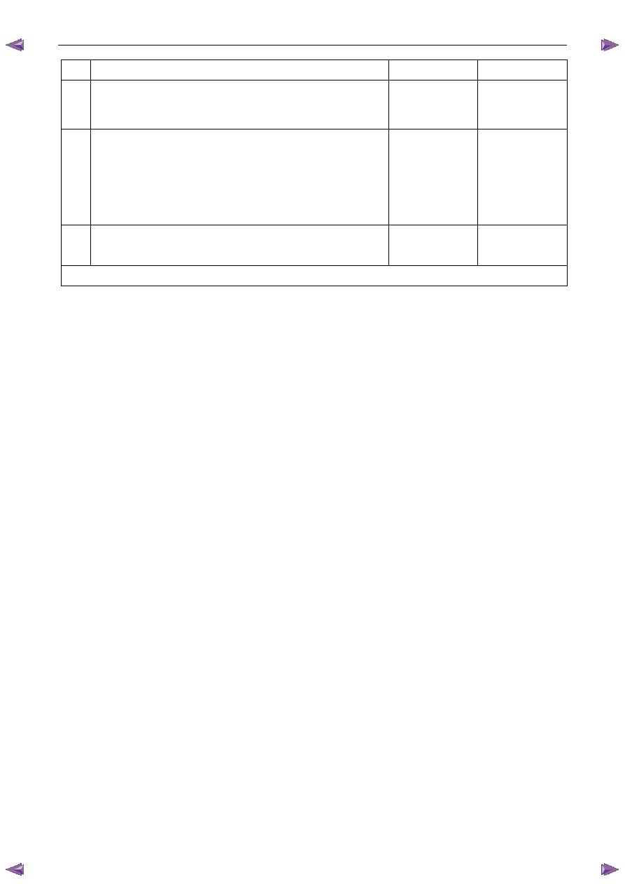
10 Replace the ECM. Refer to 6C1-3 Engine Management – V6 –
Service Operations.
Was the repair completed?
Go to Step 11
—
11 1
Using Tech 2, clear the DTCs.
2
Switch off the ignition for 30 seconds.
3
Start the engine.
4
Operate the vehicle within the conditions for running the DTC.
Does any of the CMP Sensor Circuit DTCs fail this ignition cycle?
Go to Step 2
Go to Step 12
12 Using Tech 2, select the DTC display function.
Does Tech 2 display any DTCs?
Go to the
appropriate DTC
Table in this Section
System OK
When all diagnosis and repairs are completed, check the system for correct operation.
7.22 DTC P0351, P0352, P0353, P0354, P0355,
P0356, P2300, P2301, P2303, P2304,
P2306, P2307, P2309, P2310, P2312,
P2313, P2315 or P2316
DTC Descriptors
This diagnostic procedure supports the following DTCs:
•
DTC P0351 – Ignition Coil Cylinder 1 Circuit Malfunction
•
DTC P0352 – Ignition Coil Cylinder 2 Circuit Malfunction
•
DTC P0353 – Ignition Coil Cylinder 3 Circuit Malfunction
•
DTC P0354 – Ignition Coil Cylinder 4 Circuit Malfunction
•
DTC P0355 – Ignition Coil Cylinder 5 Circuit Malfunction
•
DTC P0356 – Ignition Coil Cylinder 6 Circuit Malfunction
•
DTC P2300 – Ignition Coil Cylinder 1 Circuit Low Voltage
•
DTC P2301 – Ignition Coil Cylinder 1 Circuit High Voltage
•
DTC P2303 – Ignition Coil Cylinder 2 Circuit Low Voltage
•
DTC P2304 – Ignition Coil Cylinder 2 Circuit High Voltage
•
DTC P2306 – Ignition Coil Cylinder 3 Circuit Low Voltage
•
DTC P2307 – Ignition Coil Cylinder 3 Circuit High Voltage
•
DTC P2309 – Ignition Coil Cylinder 4 Circuit Low Voltage
•
DTC P2310 – Ignition Coil Cylinder 4 Circuit High Voltage
•
DTC P2312 – Ignition Coil Cylinder 5 Circuit Low Voltage
•
DTC P2313 – Ignition Coil Cylinder 5 Circuit High Voltage
•
DTC P2315 – Ignition Coil Cylinder 6 Circuit Low Voltage
•
DTC P2316 – Ignition Coil Cylinder 6 Circuit High Voltage
Circuit Description
The engine control relay applies positive voltage to the ignition voltage circuit of the ignition coil and the ignition coil dual
line ground circuits are directly connected to ground.