Isuzu KB P190. Manual - part 829
Engine Management – V6 – Diagnostics
Page 6C1-2–38
Step Action Value(s)
Yes
No
3
1
Disconnect the fuel injector harness connector,
refer to 2.13 Fuel Rail Assembly, in 6C1-3 Engine
Management – V6 – Service Operations.
2
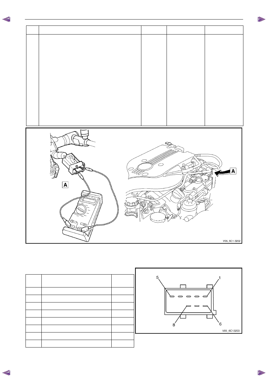
Using a digital ohmmeter and connector test
adaptor kit J 35616-A, measure the resistance of
each fuel injector between the ignition voltage
circuit and the fuel injector control circuit. Refer to
8A Electrical - Body and Chassis for information
on testing for continuity and to Figure 6C1-2 – 9
and Figure 6C1-2 – 10 for the fuel injector
harness connector.
3
Record each fuel injector value.
4
Subtract the lowest resistance value from the
highest.
Is the difference equal to, or less than, the specified
value?
3
Ω
Injectors OK
Refer to Injector
Coil Test – With
Special Tool J39021
in this Section.
Figure 6C1-2 – 9
Fuel Injector Harness to Engine Harness Connector
Pin Description
Pin Function
Circuit
Number
1
Ignition Voltage Circuit – Cyl. 1, 3, 5
639
2
Ignition Voltage Circuit – Cyl. 2, 4, 6
1039
3
Injector 1 Control Circuit
1744
4
Injector 3 Control Circuit
1746
5
Injector 5 Control Circuit
845
6
Injector 2 Control Circuit
1745
7
Injector 4 Control Circuit
844
8
Injector 6 Control Circuit
846
Figure 6C1-2 – 10