Isuzu KB P190. Manual - part 761
Engine Mechanical – V6
Page 6A1–267
Page 6A1–267
CAUTION
Do not damage the crankshaft journal,
cylinder wall and piston cooling jets when
removing the connecting rod and piston
assembly.
12
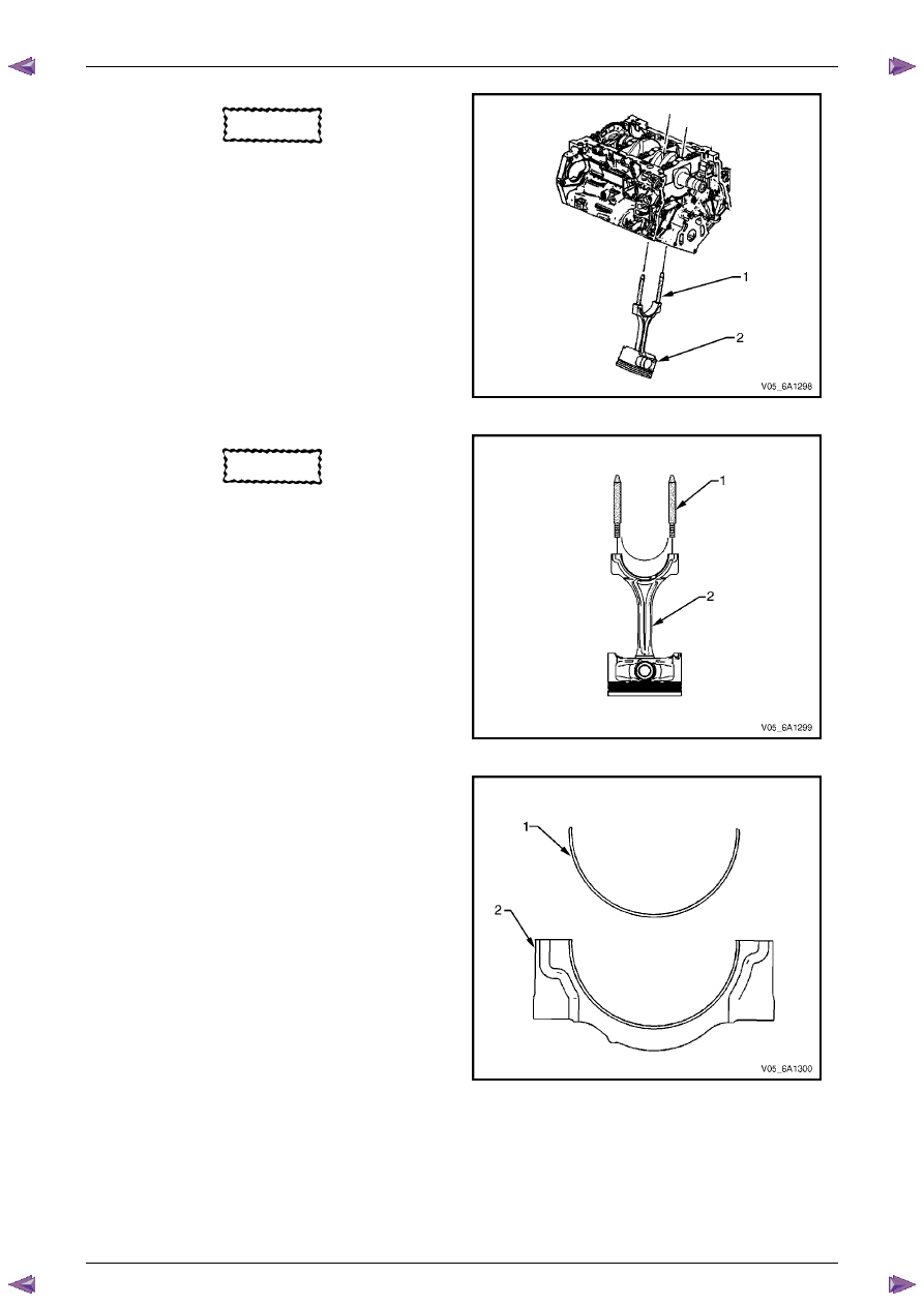
Using connecting rod guide pin set, Tool No.
EN-46121 (1), push the connecting rod and piston
assembly (2) through the top of the cylinder.
Figure 6A1 – 467
CAUTION
When dismantled, ensure the connecting
rod, connecting rod cap, piston and
bearings are organised in their original
position and location. This will also aid
engine mechanical diagnosis.
13
Remove connecting rod guide pin set, Tool No.
EN-46121 (1) from the connecting rod bolt holes.
14
Remove the upper connecting rod bearing from the
connecting rod (2).
Figure 6A1 – 468
15
Remove the lower connecting rod bearing (1) from
the connecting rod cap (2).
Figure 6A1 – 469