Isuzu KB P190. Manual - part 672
Engine Mechanical – V6
Page 6A1–209
d
If the endplay exceeds the specified limits, measure the width of the crankpin end of the connecting rod, refer
to 5
Specifications.
e
If the connecting rod width is significantly smaller than specified and severe wear is present on the side of the
connecting rod, replace the connecting rod.
f
If the connecting rod width is within specification and excessive scoring is present on the crankshaft journals,
replace the crankshaft.
CAUTION
Do not use a stamp, punch or any other
method that may distort or stress the
connecting rod and cap. Extensive engine
damage may result from a connecting rod that
is distorted or stressed.
8
Mark the cylinder number on the connecting rod and the connecting rod cap with a paint stick or permanent marker.
CAUTION
Powdered metal connecting rods have rod
bolts which yield when tighten to the
specified torque. If the bolts are loosened or
removed they must be replaced. Rod bolts
that are not replaced will not torque to the
correct clamp load and can lead to serious
engine damage.
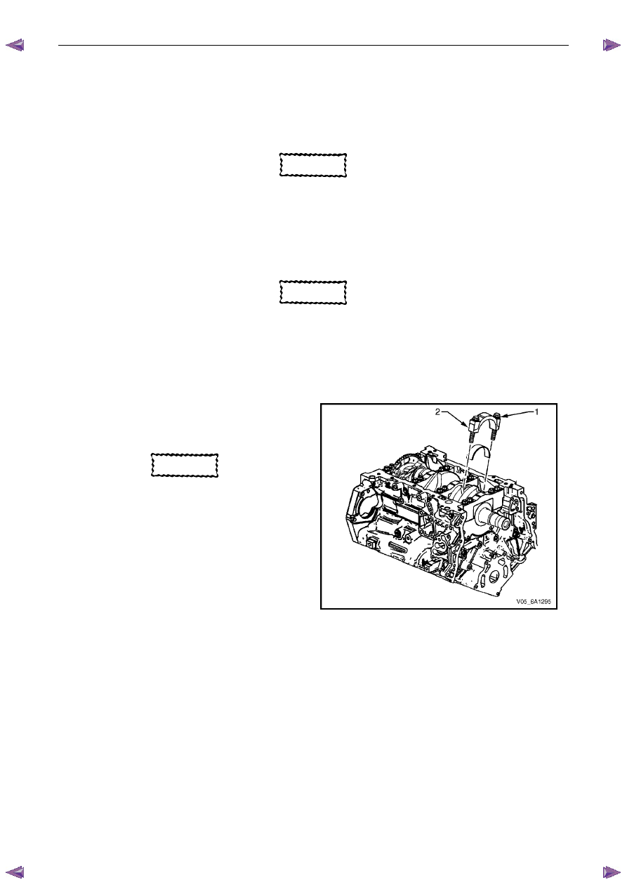
9
Remove the connecting rod bolts (1), loosening
progressively from side to side.
CAUTION
The connecting rod caps must remain with
the original connecting rod.
10
Remove the connecting rod cap (2).
Figure 6A1 – 375