Isuzu KB P190. Manual - part 661
 

  Index      Isuzu     Isuzu KB P190 - service repair manual 2007 year


Search            


Content   ..  659  660  661  662   ..


Isuzu KB P190. Manual - part 661


Engine Mechanical – V6 

Page 6A1–165 


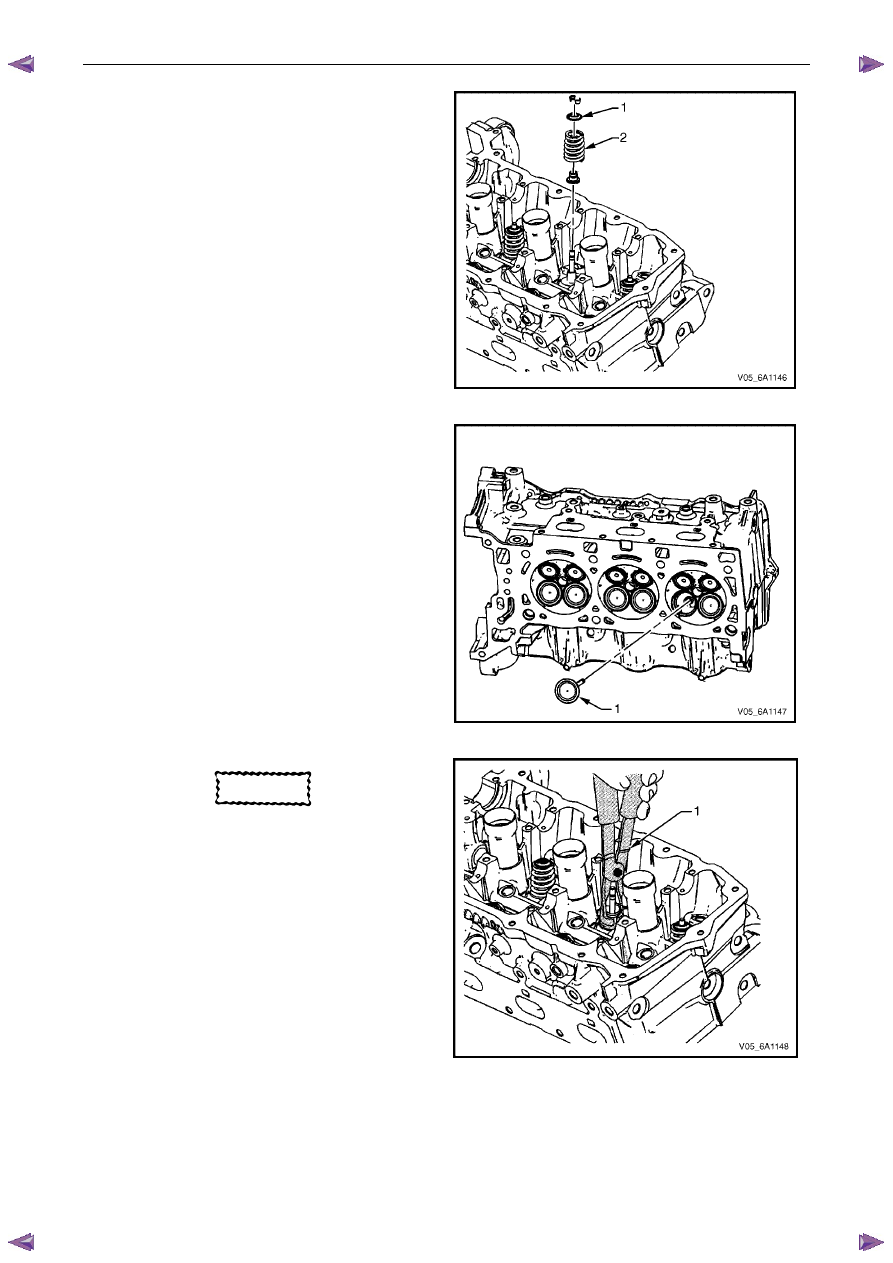
Remove the valve spring retainer (1). 

Remove the valve spring (2). 


Figure 6A1 – 282 

Remove the valves (1). 


Figure 6A1 – 283 

CAUTION


Never reuse a valve stem oil seal. 

Remove the valve stem oil seal using Tool No.  
EN-46116 and discard. 

Repeat these procedures for the remaining valves. 


Figure 6A1 – 284 

Engine Mechanical – V6 

Page 6A1–166 


10 

Remove the cylinder head oil gallery expansion 
plugs (1). 


Figure 6A1 – 285 

11 

Remove the cylinder head coolant threaded plugs (1).


Figure 6A1 – 286 

Clean 

CAUTION


Due to the aluminium alloy construction of 
the cylinder head, wire brushes and steel 
scrapers must not be used during the 
cleaning process, as damage to sealing 
surfaces may occur. Use a wood or plastic 
scraper as an alternative. 

Remove any old thread sealant, gasket material or sealant using commercially available plastic or wooden scraper. 

Clean all cylinder head surfaces with non-corrosive solvent. 


Safety glasses must be worn when using 
compressed air. 

Blow out all the oil galleries using compressed air. 

Remove any carbon deposits from the combustion chambers. 

Clean any debris or build-up from the lifter pockets. 

Engine Mechanical – V6 

Page 6A1–167 


Inspect 

Visual Inspection 

Inspect the cylinder head (1) camshaft bearing 
surfaces for the following conditions: 
• 

excessive scoring or pitting, 

• 

discoloration from overheating, and 

• 

deformation from excessive wear. 

If any of the above conditions exist on the camshaft 
bearing surfaces, replace the cylinder head. Do not 
machine the camshaft bearing journals. 


Figure 6A1 – 287 

Inspect the cylinder head for the following: 
• 

Cracks, damage or pitting in the combustion chambers. 

• 

Debris in the oil galleries. continue to clean the galleries until all debris is removed. 

• 

Coolant leaks or damage to the deck face sealing surface. if coolant leaks are present, measure the surface 
warpage as described under Cylinder Head Measurement within this Section. 

• 

Burrs or any defects that would degrade the sealing of a new secondary camshaft chain tensioner gasket. 

• 

Damage to any gasket surfaces. 

• 

Damage to any threaded bolt holes. 

• 

Burnt or eroded areas in the combustion chamber. 

• 

Cracks in the exhaust ports and combustion chambers. 

• 

External cracks in the water passages. 

• 

Restrictions in the intake or exhaust passages. 

• 

Restrictions in the cooling system passages. 

• 

Rusted, damaged or leaking core plugs. 

If the cylinder head is cracked or damaged, it must be replaced. No welding or patching of the cylinder head is 
recommended. 

Cylinder Head Measurement 

N O T E  

For all cylinder head and associated component 
specifications, refer to 5 

Specifications. 

Camshaft Journal Clearance 

Install the camshaft bearing cap in the cylinder head without the camshaft. 

Install the camshaft cap bolts and tighten to the correct torque specification 

Camshaft bearing cap attaching bolt........8.0 – 12.0 Nm. 

Measure the camshaft bearings using an inside micrometer. 

Subtract the camshaft journal diameter from the camshaft bearing diameter. This will provide the running clearance. 

If the running clearance exceeds specifications and the camshaft journals are within specification, replace the 
cylinder head. 

Camshaft Journal Alignment 

Ensure the camshafts are serviceable, refer to 3.19 

Camshaft for measuring procedures. 

Engine Mechanical – V6 

Page 6A1–168 


Inspect the cylinder head camshaft bearing surfaces for any imperfections or scratches that could inhibit correct 
camshaft clearances. Repair minor imperfections or scratches. 

Install the camshafts in the cylinder head. 

Install the camshaft bearing caps. 

Install the camshaft cap bolts and tighten to the correct torque specification. 

Camshaft bearing cap attaching bolt........8.0 – 12.0 Nm. 

Ensure the camshafts spin freely in the cylinder head. If the camshaft does not run freely, replace the cylinder head. 

Deck Flatness Inspection 

Ensure the cylinder head decks are clean and free of 
gasket material. 

Inspect the surface for any imperfections or scratches 
that could inhibit correct cylinder head gasket sealing.

Place a straight-edge (1) diagonally across the 
cylinder head (2) deck face surface. 

Measure the clearance between the straight-edge 
and the cylinder head deck face using a feeler gauge 
at four points along the straight-edge. 

If the warpage is less than 0.05 mm, the cylinder 
head deck surface does not require resurfacing. 

If the warpage is between 0.05±0.20 mm or any 
imperfections or scratches that could inhibit correct 
cylinder head gasket sealing are present, the cylinder 
head deck surface requires resurfacing. 

If resurfacing is required the maximum amount that 
can be removed is 0.25 mm. 

If the cylinder head deck surface requires more than 
0.25 mm material removal the head must be 
replaced. 

Figure 6A1 – 288 


Content   ..  659  660  661  662   ..