Isuzu KB P190. Manual - part 643
 

  Index      Isuzu     Isuzu KB P190 - service repair manual 2007 year


Search            


Content   ..  641  642  643  644   ..


Isuzu KB P190. Manual - part 643


Engine Mechanical – V6 

Page 6A1–93 


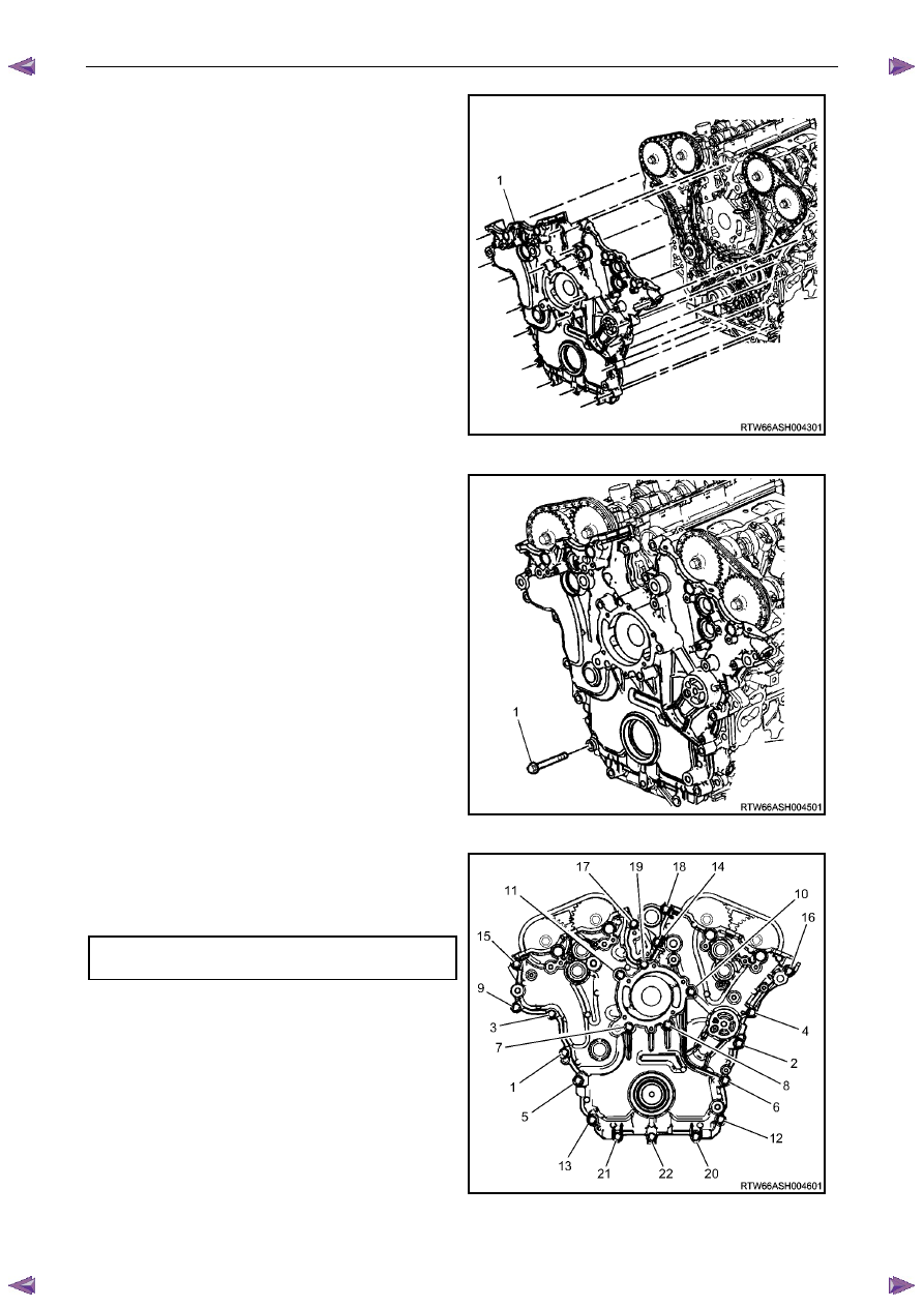
Place the front cover onto the special tools and slide 
into position. 

Remove the special tools from the cylinder block. 

Figure 6A1 – 96 

Hand start the front cover bolts (1). 

Figure 6A1 – 97 

Tighten the engine front cover bolts to the correct 
torque specification, in the sequence shown. 


Engine front cover assembly attaching  
bolt torque specification ..........................20.0 – 26.0 Nm 


Fill the cooling system, refer to 6B1 Engine Cooling – 
V6. 

Change the engine oil, refer to 3.1 

Engine Oil. 


Figure 6A1 – 98 

Engine Mechanical – V6 

Page 6A1–94 


3.16  Timing Chains, Tensioners, Shoes and 

Guides 

CAUTION


Setting the camshaft timing is required 
whenever the camshaft drive system has 
been disturbed and the relationship between 
any chain and sprocket has been lost. If 
required, follow the left-hand secondary 
timing chain reinstallation procedure to reset 
the camshaft timing. 

Primary and Left-hand Secondary Timing Chain Installation 


Figure 6A1 – 99 

Legend 

Intake Camshaft Sprocket Timing Mark – Left-hand 

Secondary Timing Chain Bright Plated Link – Left-hand 

Exhaust Camshaft Sprocket Timing Mark – Left-hand 

Secondary Timing Chain – Left-hand 

Primary Timing Chain 

Camshaft Intermediate Driveshaft Sprocket Timing Mark – 
Left-hand 

7  

Camshaft Intermediate Driveshaft Sprocket – Left-hand 

Primary Timing Chain Bright Plated Link 

Camshaft Intermediate Driveshaft Sprocket Timing Mark – 
Left-hand 

10  

Camshaft Intermediate Drive shaft Sprocket – Right-hand 

11  

Crankshaft Sprocket 

12 

Crankshaft Sprocket Timing Mark 

Engine Mechanical – V6 

Page 6A1–95 


Right-hand Secondary Timing Chain Installation 


Figure 6A1 – 100 

Legend 

Intake Camshaft Sprocket Timing Mark – Left-hand 

Secondary Timing Chain Bright Plated Link – Left-hand 

Exhaust Camshaft Sprocket Timing Mark – Left-hand 

Secondary Timing Chain – Left-hand 

Primary Timing chain 

Camshaft Intermediate Drive Chain Sprocket Timing Mark – 
Left-hand 

7  

Primary Camshaft Intermediate Drive Chain Sprocket – Left-
hand 

Primary Timing Chain Bright Plated Link 

Camshaft Intermediate Drive Chain Sprocket Timing Mark – 
Left-hand 

10  

Camshaft Intermediate Drive Chain Sprocket – Right-hand

11  

Crankshaft Sprocket 

12 

Crankshaft Sprocket Timing Mark 

13 

Secondary Timing chain Bright Plated Link – Right-hand 

14 

Camshaft Intermediate Drive Chain – Right-hand 

15 

Exhaust Camshaft Sprocket Timing Mark - Right-side 

16 

Inlet Camshaft Sprocket Timing Mark - Right-side 

Engine Mechanical – V6 

Page 6A1–96 


Remove 

Right-hand Secondary Timing Chain 

CAUTION


After removing the upper intake manifold, and 
spark plugs, plug any openings to prevent dirt 
and other contaminants from entering. 

Remove the engine front cover assembly, refer to 3.15 

Front Cover Assembly. 

Remove the spark plugs to aid crankshaft/engine rotation, refer to 6C1-3 Engine Management – V6 – Service 
Operations. 

Install Tool No. EN46111 (1) onto the crankshaft (2).

Figure 6A1 – 101 

Using Tool No. EN46111 (1), rotate the crankshaft in 
a clockwise direction until the crankshaft sprocket 
timing mark (2) is aligned with the indexing mark (3) 
on the oil pump housing. 

Figure 6A1 – 102 


Content   ..  641  642  643  644   ..