Isuzu KB P190. Manual - part 539
 

  Index      Isuzu     Isuzu KB P190 - service repair manual 2007 year


Search            


Content   ..  537  538  539  540   ..


Isuzu KB P190. Manual - part 539


6D3-8  STARTING AND CHARGING SYSTEM 


General On-Vehicle Inspection 

The operating condition of charging system is indicated by the 
charge warning lamp. The warning lamp comes on when the 
starter switch is turned to "ON" position. The charging system 
operates normally if the lamp goes off when the engine starts.
If the warning lamp shows abnormality or if undercharged or 
overcharged battery condition is suspected, perform diagnosis 
by checking the charging system as follows: 
1.  Check visually the belt and wiring connector. 

2. With the engine stopped, turn the stator switch to "ON"

position and observe the warning lamp. 


If lamp does not come on: 

  Disconnect wiring connector from generator, and ground

the terminal "L" on connector side. 


If lamp comes on: 


Repair or replace the generator. 


Generator 

Removal 

1.  Disconnect battery ground cable. 

2.  Move drive belt tensioner to loose side using wrench then

remove drive belt. 

3.  Disconnect terminal "B" wiring connector and connector. 

4.  Remove generator assembly. 


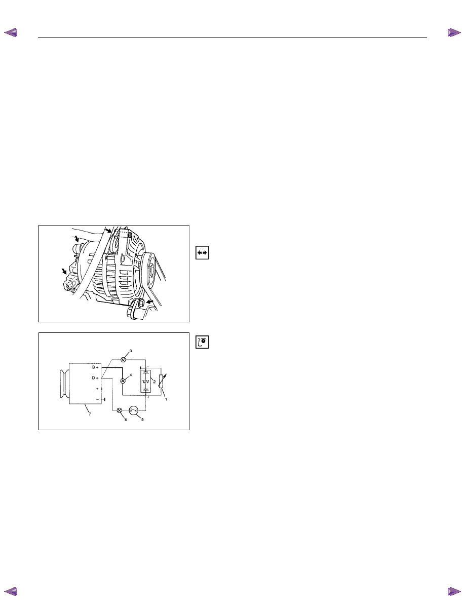
Generator Power and Circuit Diagram


Inspection 

Legend 

1 Load resistor, set parallel to battery 
2 Battery 
3 Voltmeter 
4 Ammeter 
5 Ignition Lock 
6 Charge Telltale 
7 Generator 
 

1. Disconnect battery. 

2.  Close off connecting cable from alternator terminal "B+". 

3.  Set ammeter (measuring range 100A) in disconnected line.

4.  Connect controllable load resistor to battery terminal. 

5.  Set resistor in front of connection to "O"; connect first to

battery, then to resistor. 

6. Connect tachometer. 

7. 

Connect oscilloscope according to manufacturer's

instructions. 

8. Connect battery. 

9.  Start engine and read off resulting current at various engine

speeds. 


STARTING AND CHARGING SYSTEM  6D3-9 


Generator Power 

1.  Adjust load resistor, if the required load currents are not 

attained. 

2. The shape of the voltage curves on oscilloscope curve

should be regular. 

3.  Test value: 5 to 7A. 

4.  If the required minimum current intensity is not attained, or

if the oscilloscope picture shows variations, the alternator

should be overhauled. 


Regulated Voltage Circuit Diagram


Legend 

1 Battery 
2 Ignition Lock 
3 Charge Telltale 
4 Resistor, for attainment of load current with the battery set in 

series 

5 Voltmeter 
6 Ammeter 
7 Generator 


Installation 

1.  Install generator assembly and bring generator assembly to

the position to be installed. 

2. Install generator assembly and tighten to the specified

torque. 


Torque: 


Long bolt: 35 N

⋅⋅⋅⋅m (3.6 kgf⋅⋅⋅⋅m) 


Short bolt: 20 N

⋅⋅⋅⋅m (2.0 kgf⋅⋅⋅⋅m) 

3.  Connect wiring harness connector. 

4.  Move drive belt tensioner to loose side using a wrench, then

install drive belt to normal position. 

5. Reconnect battery ground cable. 


6D3-10  STARTING AND CHARGING SYSTEM 


The generator has four external connections; the "B+" lead to 
battery positive, "L" lead to the warning lamp circuit(max. 2 
watts), "S" lead to battery positive terminal for battery sensing 
and an earth connection. 


Explanation of type inscripiton 

Example:KC-A--> 14V 50-90A. 
 

= Code for Stator OD(126mm OD). 

= Compact Generator. 

= Ausland (countries other than Germany) 

= Direction of rotation(clockwise). 

14V = Generator Operating Voltage. 
50A = Stabilised output at 25 C at 1800 RPM./13.5  
  

Volts. 

90A = Stabilised output at 25 C at 1800 RPM./13.5  
  

Volts. 


Generator Connetions. 

B+  :  Battery Main Connection (battery positive) 

:  Battery Sense Connection(battery positive) 

:  Waring lamp(via warning lamp to Ignition switch) 


BATT.SENSE

REGULATOR ASSEMBLY

HYBR10

ALTERNATOR ASSEMBLY

12V BATT.

1GN.SW.

300a*

WARN.LAMP

1.2 WATT

L

S

8+

SUPPRESSOR
CAPACITOR
0.5

µf

NOTE: * RESISTOR IS RECOMMENDED TO 

ENSURE THAT THE GENERATOR 
REMAINS FUNCTIONAL IN CASE OF 
WARNING LAMP FAILURE


STARTING AND CHARGING SYSTEM  6D3-11 


Warning  

Do not reverse S and L connections as this will destroy the 
warning lamp circuit of the regulator. 
Ensure good electrical contact beween generator  earth and 
battery negative, 


Operation 

With the Iginiton switch turnded "ON", current is supplied via 
the warning lamp to the "L" terminal of the regulator. Base 
current is fed to T15 causing it to turn on, current then flows 
from B+ through the rotor winding via the regulator brushes 
and the collector emitter junction of T15 to earth completing 
the circuit.  The current in the rotor causes a magnetic field 
between adjacent poles to be created, this field is rotated and 
cuts the windings of the stator at right angles inducing a 
voltage into them. 
As the speed is increased this induced voltage increases and 
results in curent being rectified in the 3 phase diode bridge and 
supplied as DC to the B+ output and hence to the battery. 
When the voltage at the B+ terminal of the battery reaches 
around 14.2 volts, this voltage is monitored by the "S" lead and 
turns the regulator Hybrid base current to T15 OFF removing 
rotor current, resulting in a decrease in output voltage to below 
the regulating voltage, T15 base current turns ON and the 
whole cycle is repeated very rapidly. 
D38 protects T15 and the regulator against the back voltage 
developed across the rotor winding when T15 turns OFF. 
The new generated EP regulators incorporate current limiting 
in the warning lamp circuit. 


Backup Regulation 

The EP regulator will limit the output voltage to a safe level 
should either the main B+ cable or the battery sense wire 
become decoupled, the output voltage will be slightly above the 
normal setting(1-3 volts). 


Start up phase 

When the Iginition switch is turned on and the engine is not 
running, the current to the rotor is reduced by switching it on 
and off at a 50% duty cycle, the frequency is approximately 4 
KHz and may be audible at times. 
This is quite normal, once the engine is started normal 
regulation commences. 


Warning lamp failure 

Should the warning lamp fail, the generator will self excite by 
deriving a small current from the phase connecion allowing the 
voltage to build up to regulating level.  
Note: no filed current will flow when the engine is cranking. 


Content   ..  537  538  539  540   ..