Isuzu KB P190. Manual - part 516
6A-50 ENGINE MECHANICAL (C24SE)
Clean
Sealing surfaces.
013RW004
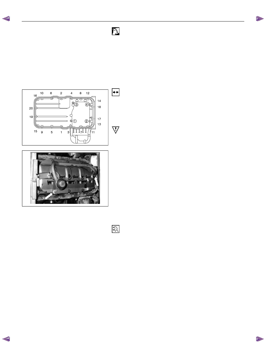
Installation
1. Apply a bead of Sealing Compound, TB120TC or
eguivalent to joint of oil pump.
2. Apply the recommended light gasket to the oil pan fitting
surface as shown in the illustration.
3. Install the bearing bridge.
4. Install baffle plate, or reuse baffle plate.
Caution
Baffle plates can be retrofitted without difficulty - replace baffle
plate.
5. Install oil intake pipe to oil pump and oil intake pipe
bracket to cylinder block.
6. Install oil pan and new gasket to cylinder block and insert
bolts with Locking Compound 15 10 177 (90 167 347).
Maximum assembly time including torque check is 10
min.
7. Return the power steering unit (and front axle [4
×4 model
only]).
8. Install the crossmember.
Tighten (Torque)
Oil intake pipe to oil pump -8N
⋅m (0.8 kgf⋅m)
Oil intake pipe bracket to cylinder block - 6 N
⋅m (0.6 kgf⋅m)
Oil pan to cylinder block - 8 N
⋅m (0.8 kgf⋅m)
Bearing bridge to cylinder block – 8 N
⋅m (0.8 kgf⋅m)