Isuzu KB P190. Manual - part 233


  Index      Isuzu     Isuzu KB P190 - service repair manual 2007 year


Search            


Content   ..  231  232  233  234   ..


Isuzu KB P190. Manual - part 233


ENGINE MECHANICAL   6A – 127 


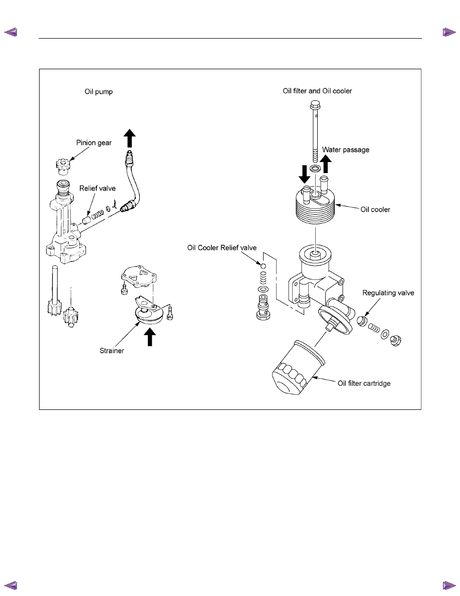
OIL PUMP AND OIL FILTER 


RTW46ALF001501 


The 4J series engine is equipped with a gear type oil pump. 

The oil filter and the water cooled oil cooler integrated a single unit to increase the cooling effect. 


6A – 128  ENGINE MECHANICAL 

OIL PUMP 

 DISASSEMBLY 


Disassembly Steps 


1. 

Oil pipe 


5. 

Driven gear 


2. 

Strainer 


6. 

Relief valve assembly 


 3. 

Pump 

cover 


 7. 

Pinion 

gear 


4. 

Driven gear with bushing 


8. 

Oil pump body 

Disassembly procedure is shown in the illustration above numerical order. 

051R100005

ENGINE MECHANICAL   6A – 129 


 INSPECTION AND REPAIR 

Make the necessary adjustments, repairs, and part replacements if excessive wear or damage is discovered during 
inspection. 

Gear Teeth and Body Inner Wall Clearance 

Use a feeler gauge to measure the clearance between the 
gear teeth and the body inner wall. 

If the clearance between the gear teeth and the body inner 
wall exceeds the specified limit, either the gear or the body 
must be replaced. 

Gear Teeth and Body Inner Wall Clearance 

mm (in)

Standard Limit 

051RY00001 

0.14 (0.0055) 

0.20 (0.0079) 


Gear and Body Clearance 

Use a feeler gauge to measure the clearance between the 
body and the gear. 

If the clearance between the gear and the body exceeds 
the specified limit, the body must be replaced. 

Gear and Body Clearance 

mm (in)

Standard Limit 


RTW46ASH002701 

0.06 (0.024) 

0.15 (0.0059) 


Drive Shaft and Oil Pump Body Clearance 

Use a micrometer to measure the drive shaft outside 
diameter. 

Use an inside dial indicator to measure the pump body 
inside diameter. 

If the clearance between the drive shaft and the oil pump 
body exceeds the specified limit, the oil pump assembly 
must be replaced. 

Drive Shaft and Oil Pump Body Clearance 

mm (in)

Standard Limit 

0.04 (0.0016) 

0.20 (0.0079) 

051RY00003

6A – 130  ENGINE MECHANICAL 


 REASSEMBLY 


Reassembly Steps 


1. 

Oil pump body 


5. 

Pinion gear 


2. 

Drive gear 


6. 

Strainer 


3. 

Driven gear 


7. 

Relief valve assembly 


 4. 

Pump 

cover 


 8. 

Oil pipe 

Reassembly procedure is shown in the illustration above numerical order. 
Pump cover fixing bolts torque: 16 N·m (1.6 kg·m/12 lb ft) 

051R100006


Content   ..  231  232  233  234   ..