Isuzu KB P190. Manual - part 216


  Index      Isuzu     Isuzu KB P190 - service repair manual 2007 year


Search            


Content   ..  214  215  216  217   ..


Isuzu KB P190. Manual - part 216


ENGINE MECHANICAL   6A – 59 


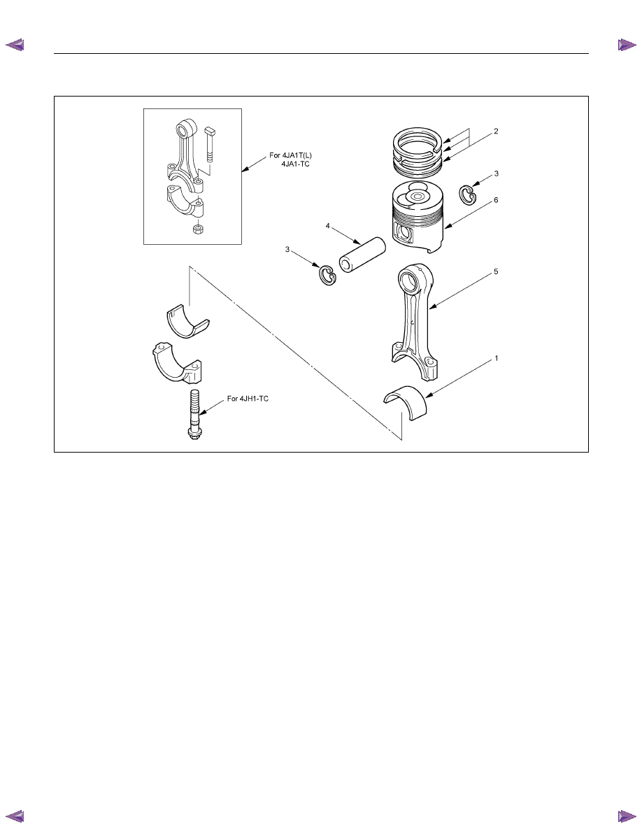
PISTON AND CONNECTING ROD 


RTW46ALF000301 


Disassembly Steps 


   1. 

Connecting rod bearing 


4. 

Piston pin 

   2. 

Piston ring 


5. 

Connecting rod 

   3. 

Piston pin snap ring 


6. 

Piston 

6A – 60  ENGINE MECHANICAL 


RTW36ASH001501 

Disassembly 

1.  Connecting Rod Bearing 

If the connecting rod bearings are to be reinstalled, mark 
their fitting positions by tagging each bearing with the 
cylinder number from which it was removed. 


015RW041 


2. Piston 

Ring 

1.  Clamp the connecting rod in a vise. 

Take care not to damage the connecting rod. 

2.  Use a piston ring replacer to remove the piston rings.

Piston Ring Replacer 

Do not attempt to use some other tool to remove the 
piston rings. Piston ring stretching will result in 
reduced piston ring tension. 


3.  Piston Pin Snap Ring 

Use a pair of pliers to remove the piston pin snap rings. 


RTW36ASH001601 


4. Piston 

Pin 

5. Connecting 

Rod 

6. Piston 

Tap the piston pin out with a hammer and a brass bar. 

If the pistons and piston pins are to be reinstalled, mark 
their installation positions by tagging each piston and piston 
pin with the cylinder number from which it was removed. 

F06MV015

ENGINE MECHANICAL   6A – 61 


 INSPECTION AND REPAIR 

Make the necessary adjustments, repairs, and part replacements if excessive wear or damage is discovered during 
inspection. 


CYLINDER HEAD 

Cylinder Head Lower Face Warpage 

1.  Use a straight edge and a feeler gauge to measure the 

four sides and the two diagonals of the cylinder head lower 
face. 

2.  The cylinder head lower surface warpage is more than the 

limit, it should be replaced. 


Cylinder Head Lower Face Warpage 

mm (in)

Standard Limit 

0.05 

(0.002) or less 

0.20 

(0.0079) 


NOTE: 

The cylinder head lower face cannot be reground. 


Cylinder Head Height (

H)

 (Reference) 

mm (in)

Standard 

91.95 – 92.05 

(3.620 – 3.624) 


Positive Crankcase Ventilation (PCV) Valve 

1.  Remove PCV valve assembly from cylinder head cover. 

2.  Inspect the diaphragm for broken. 

3.  Inspect the spring for broken or weaken. 

4.  If find any abnormal condition, replace the PCV valve 

assembly. 


011RY00012

011RY00013

011RY00014

6A – 62  ENGINE MECHANICAL 


Manifold Fitting Face Warpage 

Use a straight edge and a feeler gauge to measure the 
manifold cylinder head fitting face warpage. 
Regrind the manifold cylinder head fitting surfaces if the 
measured values are greater than the specified limit but less 
than the maximum grinding allowance. 
If the measured values exceed the maximum grinding 
allowance, the cylinder head must be replaced. 


Manifold Fitting Face Warpage 

mm (in)

Standard Limit 

Maximum Grinding 

Allowance 

0.05 

(0.002) or less 

0.20 

(0.008) 

0.40 

(0.016) 


Exhaust Manifold Warpage 

Use a straight edge and a feeler gauge to measure the 
manifold cylinder head fitting face warpage. 
If the measured values exceed the specified limit, the manifold 
must be replaced. 


Exhaust Manifold Warpage 

mm (in)

Standard Limit 

0.05 (0.002) or less 

0.20 (0.008) 


Valve Stem and Valve Guide Clearance 

Measuring Method-I 

1.  With the valve stem inserted in the valve guide, set the dial 

indicator needle to "0". 

2.  Move the valve head from side to side. 

Read the dial indicator. 

Note the highest dial indication. 
If the measured values exceed the specified limit, the valve 
and the valve guide must be replaced as a set. 


Valve Stem Clearance 

mm (in)

 Standard 

Limit 

Intake Valve 

0.039 - 0.071 

(0.0015 - 0.0028) 

0.200 

(0.008) 

Exhaust Valve 

0.064 - 0.096 

(0.0025 - 0.0038) 

0.250 

(0.0098) 

027RY00001

027RY00002

011RY00022


Content   ..  214  215  216  217   ..