Isuzu KB P190. Manual - part 174
 

  Index      Isuzu     Isuzu KB P190 - service repair manual 2007 year


Search            


Content   ..  172  173  174  175   ..


Isuzu KB P190. Manual - part 174


ANTI-LOCK BRAKE SYSTEM  5B-17 


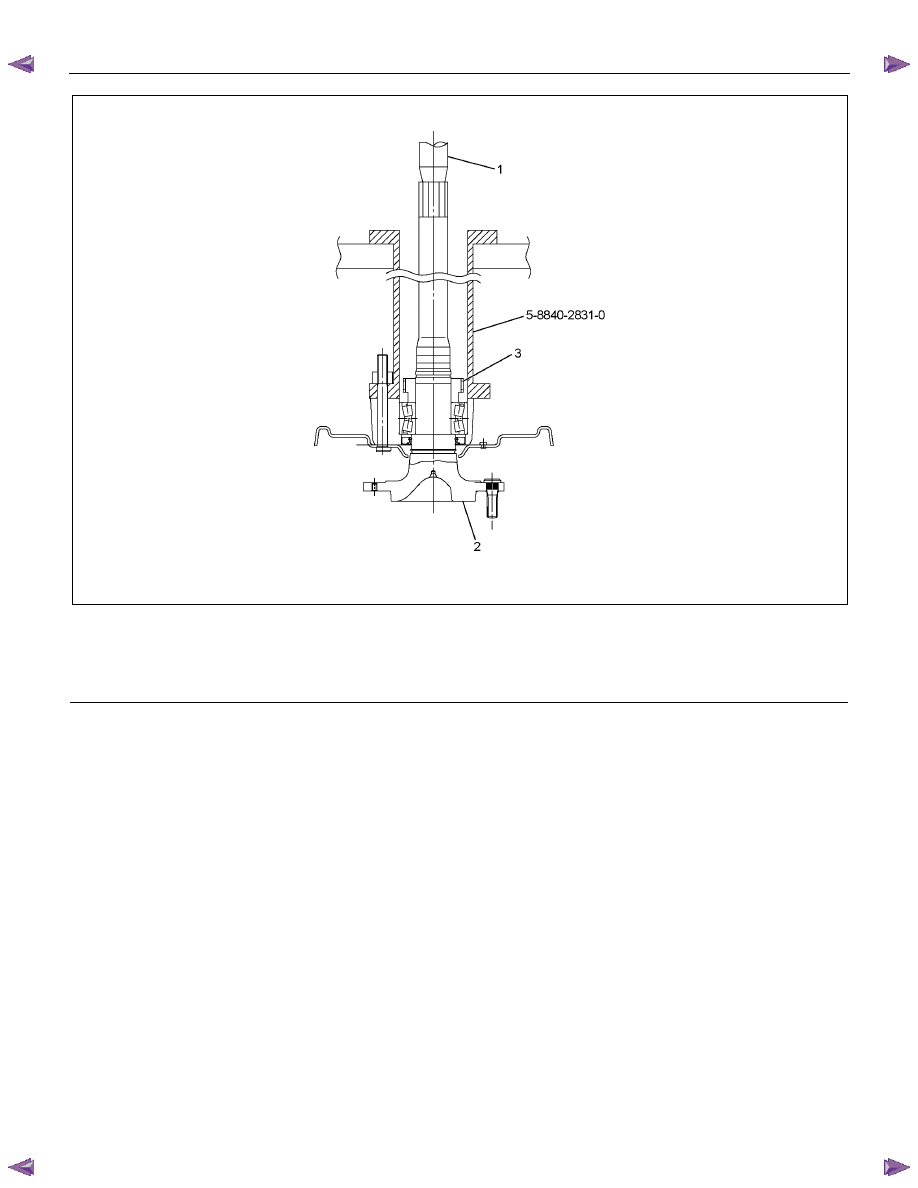
RUW55BMF000101

 
Legend 

  (1) Bench Press Fitting 

  (2) Axle Shaft 


  (3) Sensor Rotor 

Inspection and Repair 

Make all necessary adjustments, repairs or part
replacement. 

•  Check damage or powdered iron sticking to the

sensor rotor. 

•  Check play in the sensor rotor. 
•  Check a broken tooth or indentation in the sensor

rotor. 

NOTE: If replacement is required, remove the
sensor rotor from the axle shaft assembly with
brake. (Refer to the section Rear Axle). 

•  Discard the used sensor rotor. 
 

(Snap ring, Oil seal and Bearing) 

Installation 

1. Install the sensor rotor and assemble it into the

axle shaft assembly with back plate, using setting

tool 9-8522-1271-0. (Refer to the section Rear

Axle) 


5B-18  ANTI-LOCK BRAKE SYSTEM   


420R300005

Legend 

  (1) Axle Shaft 

  (2) Oil Seal 

 (3) 

Bolt 


  (4) Back Plate 

  (5) Sensor Rotor 

  (6) Double Taper Roller Bearing 


2. Install the axle shaft assembly with brake in the

rear axle. (Refer to the section Rear Axle). 


ANTI-LOCK BRAKE SYSTEM  5B-19 

G-Sensor 

G-Sensor and Associated Parts 


This illustration is based on the RHD model

RTW75BLF000101

Legend 

 (1) 

G-Sensor 


 (2) 

Nut 

Removal 

1. Remove the front floor console. (Refer to the

section Floor Console) 

2.  Disconnect the connector. 

3.  Remove the nuts. 

4.  Take out the G-sensor. 


Installation 

1.  Set the G-sensor. 

2.  Install the nut and tighten it to specified torque. 


Torque: 8 N·m (0.8 kgf·m / 69 lb·in) 

3.  Connect the connector. 

4.  Install the front floor console. (Refer to the section

Floor Console) 


5B-20  ANTI-LOCK BRAKE SYSTEM   

Special Tools 


ILLUSTRATION 

PART NO. 

PART NAME 


ILLUSTRATION 

PART NO. 

PART NAME 


5-8840-2789-0 

Installer 


9-8522-1271-0 

(J-8609-01) 

Setting Tool 


5-8840-0007-0 

(J-8092) 

Grip 


5-8840-2831-0 

Bearing Remover 


Content   ..  172  173  174  175   ..