Isuzu KB P190. Manual - part 154
BRAKE CONTROL SYSTEM 5A-23
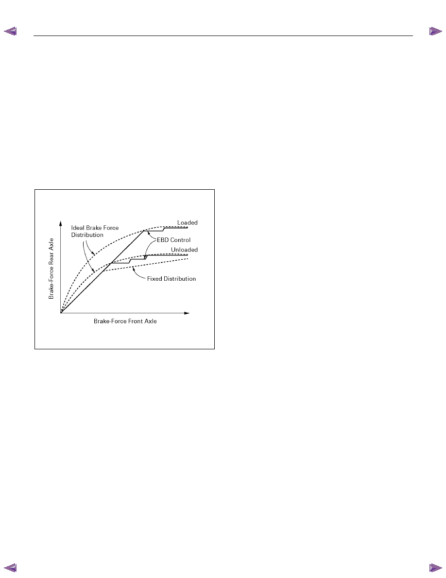
Electronic Brake-force Distribution (EBD) System
ABS has the EBD function. EBD is a function which
controls braking force distribution of a front wheel and a
rear wheel, and makes brake fluid pressure of a rear
wheel the optimal. If the rate of slip of a rear wheel
becomes greater compared to a front wheel, the brake
fluid pressure of a rear wheel will be controlled in order
to perform braking force distribution between the front
and rear wheels. EBD enables the braking power of a
rear wheel to always be utilized for the maximum
according to the load change concerning the back axis
according to the vehicle’s loading state (No luggage,
loading, etc.), deceleration, etc. Brake fluid pressure
control to a rear wheel is performed by the EBD function
which uses the ABS function without the mechanical
proportioning valve.
C05L300016
Brake Pedal Travel
Vehicles equipped with the Anti-lock Brake System may
be stopped by applying normal force to the brake pedal.
Although there is no need to push the pedal beyond the
point where it stops or holds the vehicle, by applying
more force the pedal will continue to travel toward the
floor.
This extra brake pedal travel is normal.
Acronyms and Abbreviations
Several acronyms and abbreviations are commonly
used throughout this section:
ABS
Anti-lock Brake System
CKT
Circuit
DLC
Data Link Connector
EBD
Electronic Brake-force Distribution
EHCU
Electronic Hydraulic Control Unit
FL
Front Left
FR
Front Right
GEN
Generator
H/U
Hydraulic Unit
MV
Millivolts
RR
Rear
RPS
Revolutions per Second
VDC
DC Volts
VAC
AC Volts
W/L
Warning Lamp
WSS
Wheel Speed Sensor
General Diagnosis
General Information
ABS problems can be classified into two types, those
which can be detected by the ABS warning lamp and
those which can be detected as a vehicle abnormality
by the driver.
In either case, locate the fault in accordance with the
“BASIC DIAGNOSTIC FLOWCHART” and repair.
Please refer to Section 5C for the diagnosis of
mechanical troubles such as brake noise, brake judder
(brake pedal or vehicle vibration felt when braking),
uneven braking, and parking brake trouble.
ABS Service Precautions
Required Tools and Items:
• Box Wrench
• Brake
Fluid
• Special Tool
Some diagnosis procedures in this section require the
installation of a special tool.
5-8840-0366-0 High Impedance Multimeter
When circuit measurements are requested, use a circuit
tester with high impedance.