Content .. 1421 1422 1423 1424 ..
Isuzu KB P190. Manual - part 1423
9A1-10 RESTRAINT CONTROL SYSTEM
Chart A SRS Control Unit Integrity Check
RTW79ALF000301
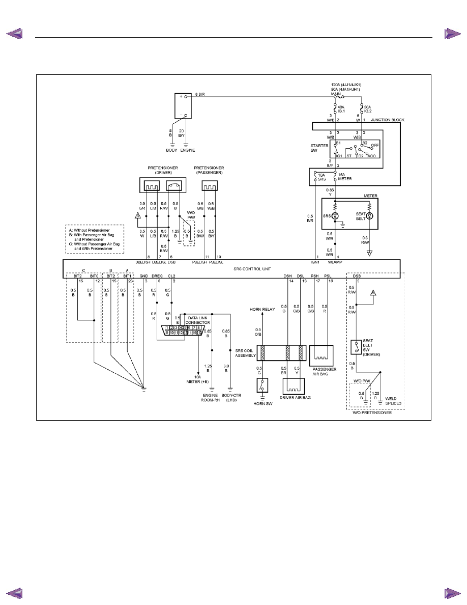
Circuit Description
When the SRS control unit recognizes that “Ignition 1”
voltage, applied to terminals “1”, is greater than 9 volts,
the “SRS” warning lamp is flashed 7 times to verify
operation. At this time the SRS control unit performs
“Turn–ON” tests followed by “Continuous Monitoring”
tests. When a malfunction is detected, the SRS control
unit sets a current diagnostic trouble code and
illuminates the “SRS” warning lamp. The SRS control
unit will clear current diagnostic trouble codes and move
them to a history file when the malfunction is no longer
detected and/or the ignition switch is cycled, except for
DTCs B0051 and B0055.
Chart Test Description
Number(s) below refer to step number(s) on the
diagnostic chart:
1. This test confirms a current malfunction. If no
current malfunction is occurring (history DTC set)
the “Diagnostic Aids” for the appropriate diagnostic
trouble code should be referenced. The SRS control
unit should not be replaced for a history diagnostic
trouble code.
2. This test checks for a malfunction introduced into the
SRS during the diagnostic process. It is extremely
unlikely that a malfunctioning SRS control unit would
cause a new malfunction to occur during the
diagnostic process.