Isuzu KB P190. Manual - part 1200


  Index      Isuzu     Isuzu KB P190 - service repair manual 2007 year


Search            


Content   ..  1198  1199  1200  1201   ..


Isuzu KB P190. Manual - part 1200


7C-22  CLUTCH 

CLUTCH 


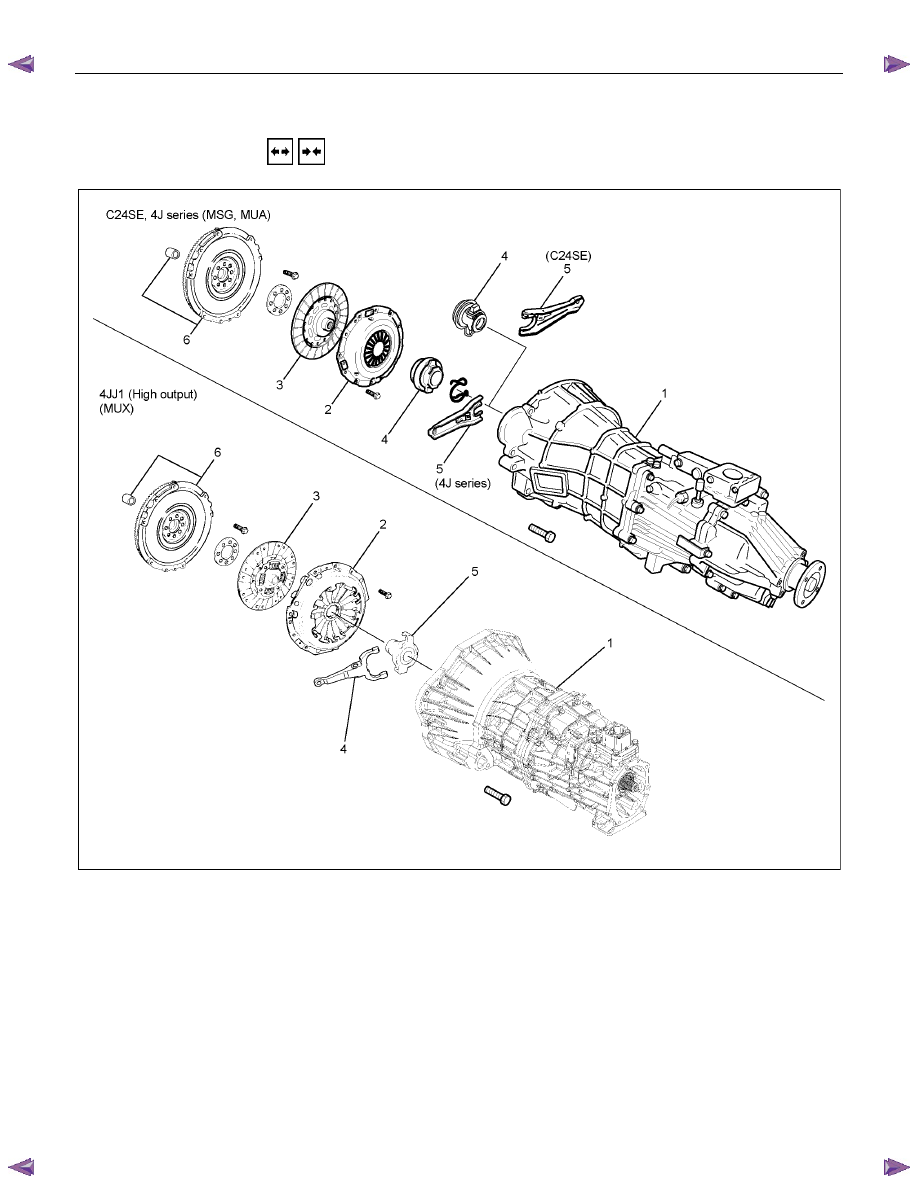
  REMOVAL AND INSTALLATION 


RTW77CLF000501 


Removal Steps 

▲  1. Transmission assembly 

▲  2. Pressure Plate assembly 

▲  3. Driven plate assembly 

4. Release bearing (MSG, MUA) 

▲  4. Shift fork (MUX) 

5. Shift fork (MSG, MUA) 

▲  5. Release bearing (MUX) 

6. Flywheel assembly and crank bearing 


Installation Steps 

6. Flywheel assembly and crank bearing 
5. Shift fork (MSG, MUA) 

▲  5. Release bearing (MUX) 

4. Release bearing (MSG, MUA) 

▲  4. Shift fork (MUX) 

▲  3. Driven plate assembly 

▲  2. Pressure Plate assembly 

1. Transmission assembly. 


CLUTCH  7C-23 


Important Operations - Removal 

1. Transmission Assembly 
Refer to “MANUAL TRANSMISSION” of section 7B and 7B1 
for “REMOVAL AND INSTALLATION” procedure. 


2. Pressure Plate Assembly 

3. Driven Plate Assembly 

(1) Use the clutch pilot aligner 

1

 to prevent the driven plate

assembly 

2

 from falling free. 


Clutch Pilot Aligner :  5-8525-3001-0(J-24547) 


4J series, C24SE (MSG, MUA) 


(2) Loosen the clutch cover bolts in the numerical order shown

in the illustration. 

(3) Remove the pressure plate assembly 

3

 from the flywheel.

(4) Remove the driven plate from the flywheel. 


4JJ1 (High Output) (MUX) 

RTW77CSH000601 


RTW77CSH000801 


4.  Shift Fork (MUX) 

5.  Release Bearing (MUX) 

(1) Remove the shift fork snap pin (2). 

(2) Remove the shift fork pin and shift fork (3) from the fulcrum

bridge. 

(3) Remove the release bearing (1) from the transmission

case. 

7C-24  CLUTCH 

015RW053 

6.  Flywheel Assembly and Crank Bearing (MUX) 

(1) Remove flywheel assembly and crankshaft bearing. Do not

remove except for replacement. 

(2) 

Use the remover 5-8840-2000-0 (J-5822) and sliding 

hammer 5-8840-0019-0 (J-23907) to remove the crankshaft 

bearing 


Important Operations - Installation 

Follow the removal procedure in reverse order to perform the 
installation procedure. 
Pay careful attention to the important points during the 
installation procedure. 
 

015RW054 

6.  Flywheel Assembly and Crank Bearing (MUX) 

(1) Install flywheel assembly and crankshaft bearing. Use the

installer 5-8840-0125-0 (J-26516-A) and driver handle 5-

8840-0007-0 (J-8092) to install the crankshaft bearing then 

clean and lubricate with grease. 

015RS047 

(2) Install new flywheel fixing bolts in the order illustrated and

tighten them to the specified torque. 

N

⋅m (kg⋅m/lb⋅ft)


MUX 54 

(5.5/40) 

NOTE: Do not reuse the bolt and do not apply oil or thread lock 
to the bolt. 


RTW77CSH000701 

5.  Release Bearing (MUX) 

4.  Shift Fork (MUX) 

(1) Apply molybdenum disulfide type grease to the pin hole

inner circumferences and thrust surfaces. 


CLUTCH  7C-25 

201RW012 

(2) 

Apply molybdenum disulfide type grease to the areas 

shown in illustration. 


(3) Install the release bearing to the transmission front cover. 

(4) Install the shift fork to the fulcrum bridge and insert the pin

from bottom of the fulcrum bridge. 

(5) Install the washer and snap pin. 


3.  Driven plate Assembly 

2.  Pressure Plate Assembly 

(1) Clean the flywheel surface. 

(2) Clean the facing surface. 

(3) Use the clutch pilot aligner 

1

 to install the driven plate 

assembly 

2

 to the flywheel 

3


Clutch Pilot Aligner :  5-8525-3001-0(J-24547) 


4


4J series, C24SE (MSG, MUA) 


(4) Clean the pressure plate surfaces. 

(5) 

Align the pressure plate assembly 

 with the flywheel 

knock pin 

5

(6) Install the pressure plate assembly to the flywheel. 

(7) Tighten the clutch cover bolts a little at a time in the

numerical order shown in the illustration. 

Clutch Cover Bolt Torque 

N

⋅m (kgf⋅m/lb⋅ft)

18 

± 3 (1.8 ± 0.3 / 13.0 ± 2.2) 


4JJ1 (High Output) (MUX) 

RTW77CSH000601 


(8) Remove the clutch pilot aligner. 

Note: 
Do not strike the clutch pilot aligner with a hammer to 
remove it.


Content   ..  1198  1199  1200  1201   ..