Isuzu KB P190. Manual - part 1042


  Index      Isuzu     Isuzu KB P190 - service repair manual 2007 year


Search            


Content   ..  1040  1041  1042  1043   ..


Isuzu KB P190. Manual - part 1042


UNIT REPAIR (AW30–40LE)

7A4–33

29. Check piston stroke of overdrive brake.

Place a dial indicator onto the overdrive brake
piston as shown in the figure.

252RY00003

Measure the stroke by applying and releasing the
compressed air (390 – 780 kPa or 57 – 114 psi) as
shown in the figure.

Piston stroke: 1.75 – 2.05 mm (0.0689 – 0.0807 in)

If the values are nonstandard, check for an improper
installation.
Available flange size

244RY00001

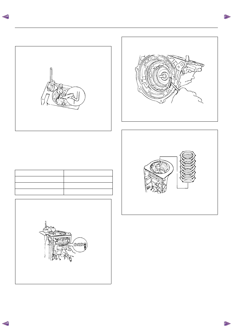
Remove the snap ring.

246RY00001

Remove one flange, four plates and four discs.

246RY00026

3.3 mm (0.130 in)

3.8 mm (0.150 in)

3.5 mm (0.138 in)

3.9 mm (0.154 in)

3.6 mm (0.142 in)

4.0 mm (0.158 in)

3.7 mm (0.146 in)

7A4–34

UNIT REPAIR (AW30–40LE)

30. Coat the bearing and races with petroleum jelly and

install them onto the overdrive support.
Bearing and races diameter (Reference)

252RY00010

31. Install the overdrive planetary ring gear.

252RY00002

32. Coat the bearing and race with petroleum jelly and

install them onto the planetary ring gear.
Bearing and race diameter (Reference)

252RY00011

Install the (flat ring) 4.0 mm (0.157 in) thick flange
with the rounded edge side of the flange facing the
disc.
Alternately install four discs and three plates. (Disc
first)
Install the (stepped ring) flange with the flat side of
the flange facing the disc.
Install the snap ring.

33. Coat the race with petroleum jelly and install it onto

the planetary gear.
Race diameter (Reference)

252RY00001

Inside

Outside

Race 

(Front)

37.2 mm (1.465 in)

58.8 mm (2.315 in)

Bearing 

and race 

(Rear)

33.7 mm (1.327 in)

50.1 mm (1.972 in)

Inside

Outside

Bearing 

and race

24.2 mm (0.953 in)

47.8 mm (1.882 in)

Inside

Outside

Race

24.7 mm (0.972 in)

41.8 mm (1.646 in)

UNIT REPAIR (AW30–40LE)

7A4–35

34. Install the overdrive planetary gear and direct clutch.

252L100001

35. Coat the assembled bearing and race with

petroleum jelly and install it onto the direct clutch.
Bearing and race diameter (Reference)

252L100018

36. Coat the race with petroleum jelly and install it onto

the oil pump.
Race diameter (Reference)

252RY00014

37. Coat the O-ring with ATF and install it around the

pump body.
Place the oil pump through the input shaft, and align
the bolt holes of the pump body with the
transmission case.
Hold the input shaft, and lightly press the oil pump
body to slide the oil seal rings on the stator shaft
through the direct clutch drum.
CAUTION:
Do not push on the oil pump strongly or the oil
seal ring will stick to the direct clutch drum.
Install the seven bolts.

Torque: 22 N·m (2.2 kgf·m/16 lb·ft)

38. Check input shaft rotation.

Make sure the input shaft rotates smoothly.

241RY00003

Inside

Outside

Bearing 

and race

28.9 mm (1.138 in)

50.2 mm (1.976 in)

Inside

Outside

Race

28.6 mm (1.126 in)

46.5 mm (1.831 in)

7A4–36

UNIT REPAIR (AW30–40LE)

Diaassembly, Inspection and
Reassembly of minor Components

NOTE:  The instructions here are organized so that you
work on only one component group at a time.
This will help avoid confusion from similar-looking parts
of different subassemblies being on your workbench at
the same time.
The component groups are inspected and repaired from
the converter housing side.
As much as possible, complete the inspection, repair
and reassembly before proceeding to the next
component group. If a component group cannot be
reassembled because parts are being ordered, be sure
to keep all parts of that group in separate container
while proceeding with disassembly, inspection, repair
and reassembly of other component groups.
Recommended ATF type DEXRON III.

General Cleaning Notes:

1. All disassembled parts should be washed clean and

any fluid passages and holes should be blown
through with compressed air.

2. When using compressed air to dry parts, always aim

away from yourself to prevent accidentally spraying
automatic transmission fluid in your face.

3. The recommended automatic transmission fluid

should be used for cleaning.

Parts Arrangement:

1. After cleaning, the parts should be arranged in

proper order to allow performing inspection, repairs,
and reassembly with efficiency.

2. When disassembling a valve body, be sure to keep

each valve together with the corresponding spring.

3. New brakes and clutches that are to be used for

replacement must be soaked in transmission fluid
for at least thirty minutes before assembly.

General Assembly:

1. All oil seal rings, clutch discs, clutch plates, rotating

parts, and sliding surfaces should be coated with
transmission fluid prior to reassembly.

2. All gaskets and rubber O-ring should be replaced.

3. Make sure that the ends of a snap ring are not

aligned with one of the cutouts and are installed in
the groove correctly.

4. If a worn bushing is to be replaced, the

subassembly containing that bushing must be
replaced.

5. Check thrust bearings and races for wear or

damage. Replace if necessary.

6. Use petroleum jelly or vaseline to keep parts in

place.


Content   ..  1040  1041  1042  1043   ..