Isuzu KB P190. Manual - part 1026


  Index      Isuzu     Isuzu KB P190 - service repair manual 2007 year


Search            


Content   ..  1024  1025  1026  1027   ..


Isuzu KB P190. Manual - part 1026


ON-VEHICLE SERVICE (AW30–40LE)  7A3-19 

ATF Replacement 

Inspection 

NOTE:  Do not overfill. 

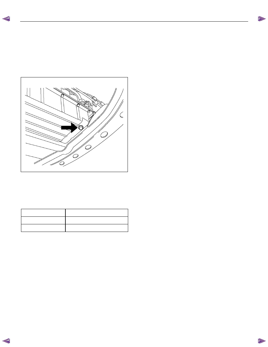
  1. Remove the drain plug from oil pan and drain the

fluid. 


RUW17ASH013401

  2. Reinstall the drain plug securely. 

Torque: 19 N

⋅⋅⋅⋅m (1.9 kgf⋅⋅⋅⋅m/14 Ib⋅⋅⋅⋅ft) 

  3. With the engine OFF, add new fluid through the filler

tube. 


Drain and refill 

5.2 liter 

Dry fill 

8.7 liter 

Fluid 

Exxon Mobil ATF-3309 


  4. Start the engine and shift the selector into all

position from “P" through “L", and then shift into “P".

 5. With the engine idling, check the fluid level. Add

fluid up to the “COLD" level on the dipstick. 

  6. The ATF level must be checked again for correct

level with the “HOT" level. 

NOTE:  To prevent fluid leaks, the drain plug gasket 
must be replaced each time this plug is removed. 


7A3-20  ON-VEHICLE SERVICE (AW30–40LE) 

Neutral Start Switch (Mode Switch) 

Inspection 

With a circuit tester, make a continuity test on the
neutral start switch with the moving piece set in each
position. 


RTW77ASH003401

Removal 

Preparation: 

Disconnect negative (–) battery cable. 

  1. Remove the rear side ATF cooler pipe from the

transmission elbow. 

  2. Disconnect neutral start switch connector. 


  3. Unstake the lock washer, and then remove the shaft 

nut. 

  4. Remove the neutral start switch. 

Installation 

To install, follow the removal steps in the reverse order,
noting the following points; 

If a engine starts at any selector position except “N” or
“P”, the neutral start switch (mode switch) should be
adjusted. 

  1. Loosen the neutral start switch bolt and set the shift 

selector to the “N" position. 

  2. Align the groove and neutral basic line. 

  3. Hold in position and tighten the bolt and nut. 

Torque: 

Nut – 7 N

⋅⋅⋅⋅m (0.7 kgf⋅⋅⋅⋅m/61 Ib⋅⋅⋅⋅in) 

Bolt – 13 N

⋅⋅⋅⋅m (1.3 kgf⋅⋅⋅⋅m/113 Ib⋅⋅⋅⋅in) 

  4. Lock the nut with the lock washer tubs at two points.


RUW17ASH013601


ON-VEHICLE SERVICE (AW30–40LE)  7A3-21 

Brake Signal 

Inspection 

Check that the brake light comes on when the brake
pedal is depressed. 


310RW020


7A3-22  ON-VEHICLE SERVICE (AW30–40LE) 

Input and Output Revolution Sensor 

Inspection 

  1. Disconnect the input and output revolution sensor

connector. 

 2. 

Use an ohmmeter to measure the resistance
between terminals 1 and 2. 

Standard resistance 

Input revolution sensor: 560 – 680 

 (at 20

°°°°C or 

68

°°°°F) 

Output revolution sensor: 560 – 680 

 (at 20

°°°°C

or 68

°°°°F) 


F07RY00018


Power and 3rd Start Switch 

Inspection 

1.  Block the wheels. 

2.  Disconnect the negative battery cable. 

3.  Pry out the switch from the floor console. 

4.  Disconnect the harness connector. 

5. Check continuity between terminals (5) and (6) at

third (3rd) position. 

6. Check continuity between terminals (3) and (6) at

power (PWR) position. 

7.  Replace the power and 3rd start switch if the result

of inspection is abnormal. 

8.  Connect the harness connector. 

9.  Connect the negative battery cable. 

10. Remove the wheel blocks. 


238R300003


Content   ..  1024  1025  1026  1027   ..