Isuzu D-Max / Isuzu Rodeo (TFR/TFS). Manual - part 813
6D3–6
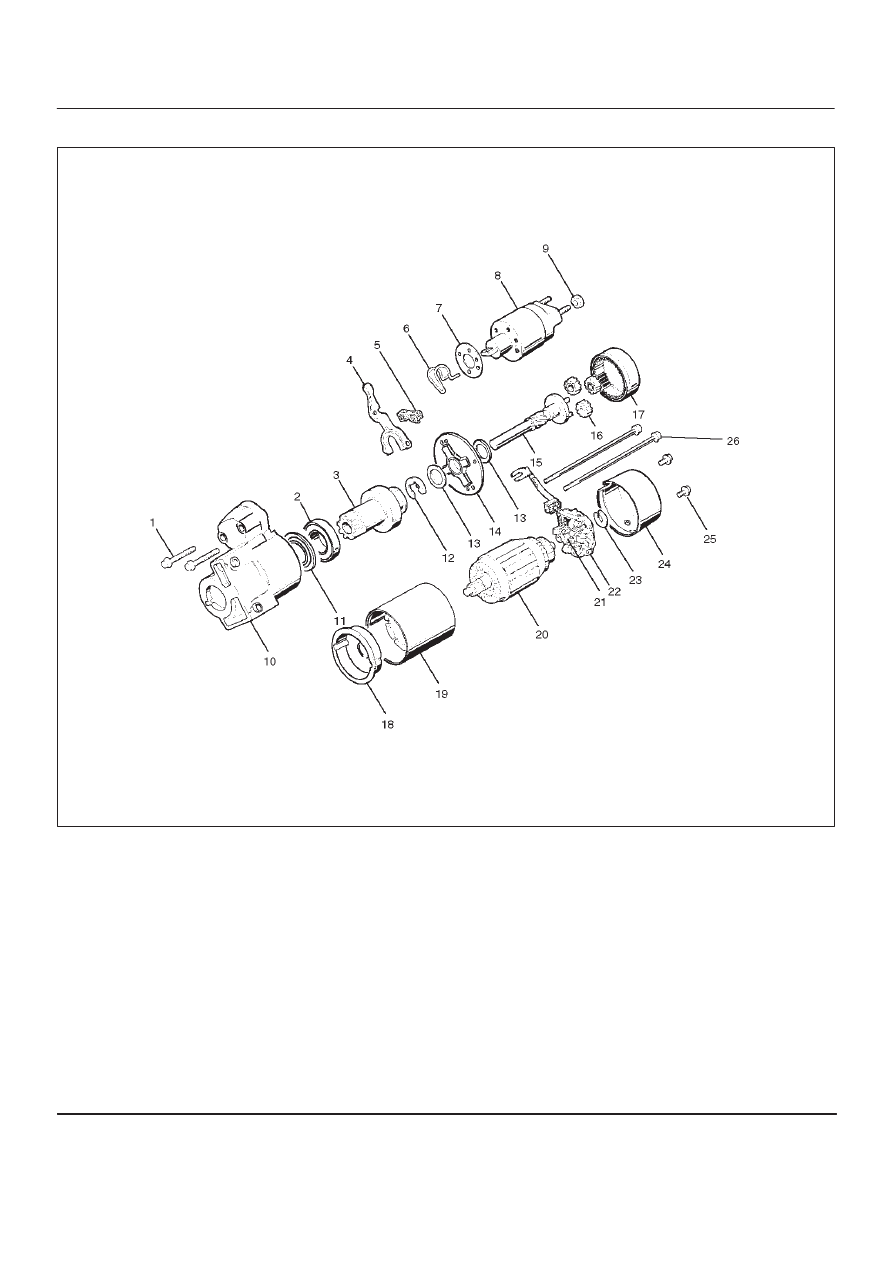
STARTING AND CHARGING SYSTEM (6VD1 3.2L)
Disassembled View
065RW002
Legend
(1) Bolt (2 pcs)
(2) Ball Bearing
(3) Pinion
(4) Shift Lever
(5) Dust Cover
(6) Torsion Spring
(7) Dust Cover
(8) Magnetic Switch
(9) Nut
(10) Gear Case
(11) Bearing Cover
(12) E–ring
(13) Thrust Washer (2)
(14) Center Bracket
(15) Pinion Shaft
(16) Planet Gear (3)
(17) Internal Gear
(18) Center Bracket (A)
(19) Yoke Assembly
(20) Armature
(21) Brush
(22) Brush Holder
(23) Thrust Washer
(24) Rear Cover
(25) Screw (2 pcs)
(26) Through Bolt (2 pcs)