Isuzu D-Max / Isuzu Rodeo (TFR/TFS). Manual - part 418
7A-220 AUTOMATIC TRANSMISSION (AW30-40LE)
243R200037
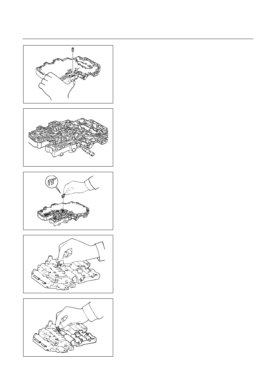
29. Retainer
Install the retainer by pushing in the plug.
243R200038
30. Throttle valve
Inset the throttle valve into the bore.
NOTE:
Check that the valve is fully inserted into the bore.
243R200039
31. Valve stopper
Install the valve stopper as shown.
243R200040
32. Adjusting ring
Turn over valve body, and install the same number of
adjusting rings as were removed during disassembly.
243R200041
33. Spring
Install the spring onto the end of the valve shaft.