Content .. 1401 1402 1403 1404 ..
Isuzu D-Max / Isuzu Rodeo (TFR/TFS). Manual - part 1403
ELECTRICAL-BODY AND CHASSIS 8-177
Switch side
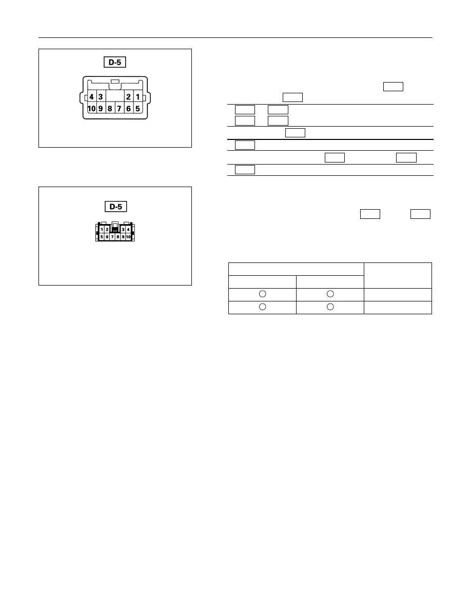
2. Switch Side Connector Circuit
Remove the switch connector, and check continuity and
voltage between the switch connector terminals.
(Connect the (+) terminal of the battery to 9
D-5
and the
(-) terminal to 5
D-5
.)
5
D-5
- 6
D-5
.................. Continuity
5
D-5
- 8
D-5
.................. Continuity
(Then, ground 3
D-5
.)
6
D-5
........... Current flow for approx. 1 second
(Disconnect the ground of 3
D-5
, and ground 4
D-5
.)
8
D-5
........... Current flow for approx. 1 second
Harness side
3. Door Lock Operation Test
After confirming that there is continuity between the switch
harness side connector terminals 6
D-5
and 8
D-5
,
apply the battery voltage to each of the terminals to conduct
the operation test.
When the door lock will not operate, check the door lock
actuator for any trouble.
Connecting terminals
8 (Y/G)
6 (L/Y)
+
-
Unlock
-
+
Lock
Operation