2017 Infiniti QX60/JX (2017 year). Manual - part 38
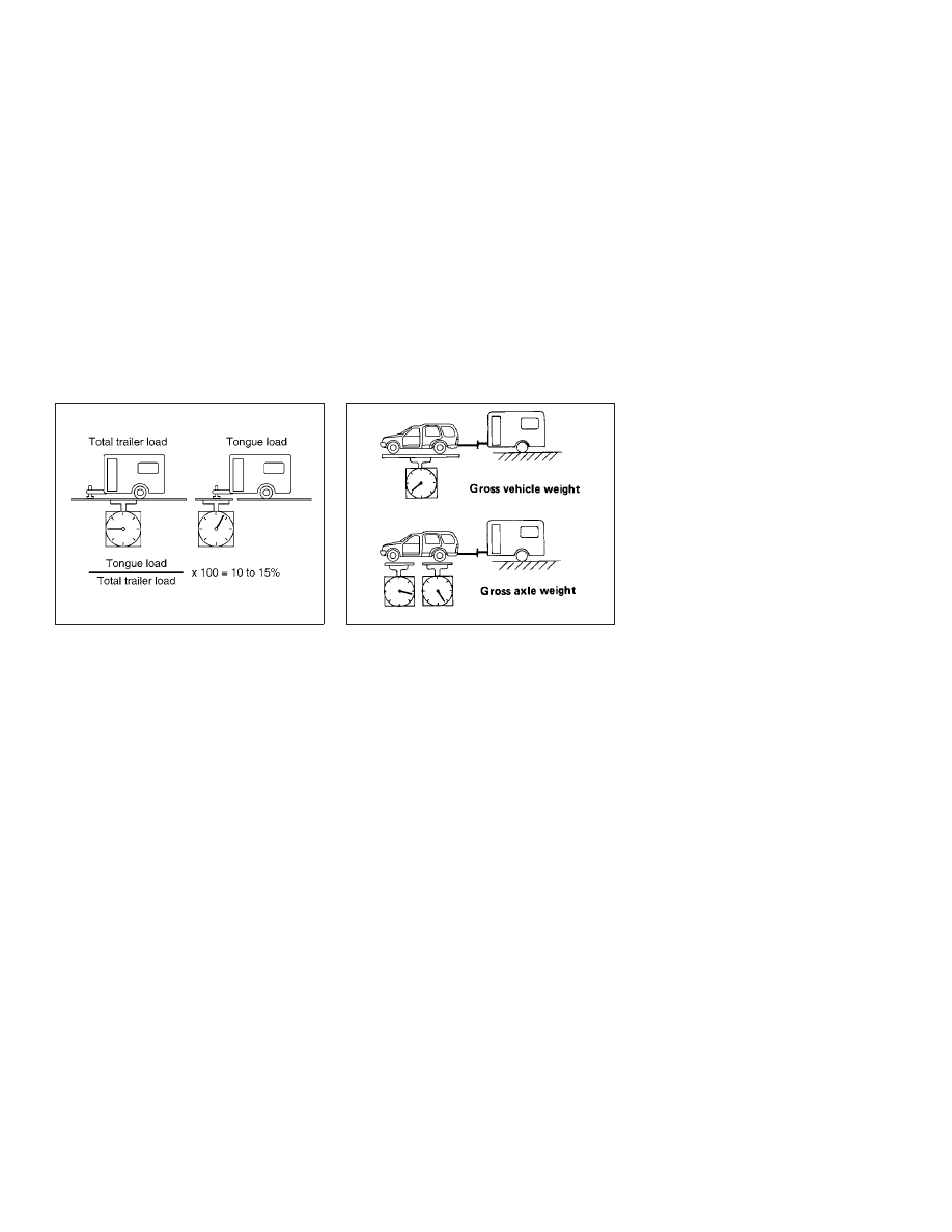
Tongue load
When using a weight carrying or a weight distrib-
uting hitch, keep the tongue load between 10 -
15% of the total trailer load or use the trailer
tongue load specified by the trailer manufacturer.
The tongue load must be within the maximum
tongue load limits shown in the following “Towing
Load/Specification” chart. If the tongue load be-
comes excessive, rearrange cargo to allow for
proper tongue load.
Maximum Gross Vehicle Weight
(GVW)/Maximum Gross Axle Weight
(GAW)
The GVW of the towing vehicle must not exceed
the Gross Vehicle Weight Rating (GVWR)
shown on the F.M.V.S.S./C.M.V.S.S. certification
label. The GVW equals the combined weight of
the unloaded vehicle, passengers, luggage,
hitch, trailer tongue load and any other optional
equipment. In addition, front or rear GAW must
not exceed the Gross Axle Weight Rating
(GAWR) shown on the F.M.V.S.S./C.M.V.S.S.
certification label.
Towing capacities are calculated assuming a
base vehicle with driver and any options required
to achieve the rating. Additional passengers,
cargo and/or optional equipment, such as the
trailer hitch, will add weight to the vehicle and
reduce your vehicle’s maximum towing capacity
and trailer tongue load.
The vehicle and trailer need to be weighed to
confirm the vehicle is within the GVWR, Front
GAWR, Rear GAWR, Gross Combined Weight
Rating (GCWR) and Towing capacity.
All vehicle and trailer weights can be measured
using platform type scales commonly found at
truck stops, highway weigh stations, building
supply centers or salvage yards.
To determine the available payload capacity for
tongue/king pin load, use the following proce-
dure.
1. Locate
the
GVWR
on
the
F.M.V.S.S./C.M.V.S.S. certification label.
2. Weigh your vehicle on the scale with all of
the passengers and cargo that are normally
in the vehicle when towing a trailer.
3. Subtract the actual vehicle weight from the
GVWR. The remaining amount is the avail-
able maximum tongue/king pin load.
WTI0160
ATI1025
Technical and consumer information
10-19