Infiniti M (2012 year). Manual - part 2
PCS
IPDM E/R
PCS-19
< ECU DIAGNOSIS INFORMATION >
[IPDM E/R]
C
D
E
F
G
H
I
J
K
L
B
A
O
P
N
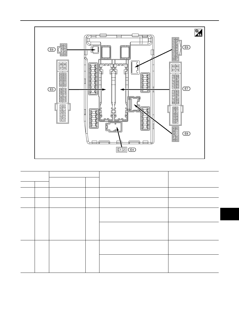
TERMINAL LAYOUT
PHYSICAL VALUES
JSMIA0001ZZ
Terminal No.
(Wire color)
Description
Condition
Value
(Approx.)
Signal name
Input/
Output
+
−
1
(W)
Ground
Battery power supply
Input
Ignition switch OFF
Battery voltage
2
(L)
Ground
Battery power supply
Input
Ignition switch OFF
Battery voltage
4
(W)
Ground
ECM relay power
supply
Output
Ignition switch OFF
(More than a few seconds after turning igni-
tion switch OFF)
0 V
• Ignition switch ON
• Ignition switch OFF
(For a few seconds after turning ignition
switch OFF)
Battery voltage
5
(P)
Ground
ECM relay power
supply
Output
Ignition switch OFF
(More than a few seconds after turning igni-
tion switch OFF)
0 V
• Ignition switch ON
• Ignition switch OFF
(For a few seconds after turning ignition
switch OFF)
Battery voltage
2012 M