Infiniti QX4. Electrical System (2003 year). Manual - part 24
SKIA1255E
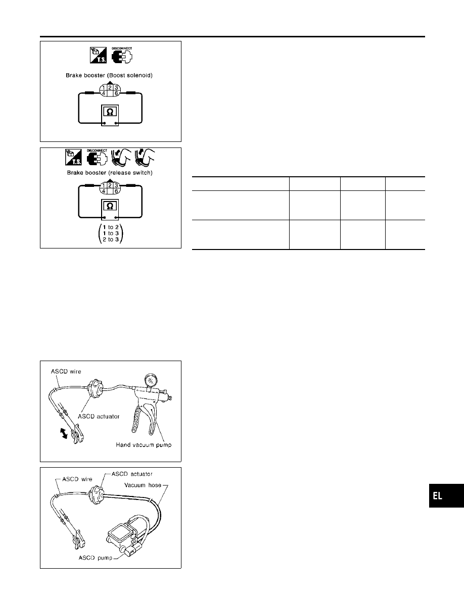
BOOSTER SOLENOID
NBEL0470S04
Disconnect booster solenoid/release switch connector, and check
resistance value between terminals 4 and 6.
4 - 6: Approx. 1.4
Ω
SKIA1256E
RELEASE SWITCH
NBEL0470S05
Disconnect booster solenoid/release switch connector and check
resistance between the terminals.
Condition
1 - 3
1 - 2
2 - 3
Release the brake pedal.
Continuity
should exist.
Continuity
should not
exist.
Continuity
should not
exist.
Depress the brake pedal.
Continuity
should not
exist. (Note)
Continuity
should exist.
(Note)
Continuity
should not
exist.
(Note): However, if pedal is depressed insufficiently, resistance value may remain
unchanged.
ASCD ACTUATOR
NBEL0470S06
1.
Disconnect vacuum hose from ASCD actuator.
PBIC0218E
2.
Connect the hose of hand vacuum pump to ASCD actuator.
Apply –40 kPa (–0.41 kg/cm
2
, –5.8 psi) vacuum to ASCD
actuator with hand vacuum pump.
ASCD wire should move to pull throttle drum.
Wait 10 seconds and check for decrease in vacuum pres-
sure.
Vacuum pressure decrease:
Less than 2.7 kPa (0.028 kg/cm
2
, 0.39 psi)
MEL402G
VACUUM HOSE
NBEL0470S07
Check vacuum hose (between ASCD actuator and ASCD pump)
for breakage, cracks or fracture.
GI
MA
EM
LC
EC
FE
AT
TF
PD
AX
SU
BR
ST
RS
BT
HA
SC
IDX
INTELLIGENT CRUISE CONTROL (ICC) SYSTEM
Electrical Component Inspection (Cont’d)
EL-373