Infiniti QX56 (JA60). Manual - part 274
DIAGNOSIS SYSTEM (TRANSFER CONTROL UNIT)
DLN-19
< FUNCTION DIAGNOSIS >
[ATX14B]
C
E
F
G
H
I
J
K
L
M
A
B
DLN
N
O
P
12. Move A/T selector lever to N position.
13. Turn 4WD shift switch to AUTO position.
14. Move A/T selector lever to P position.
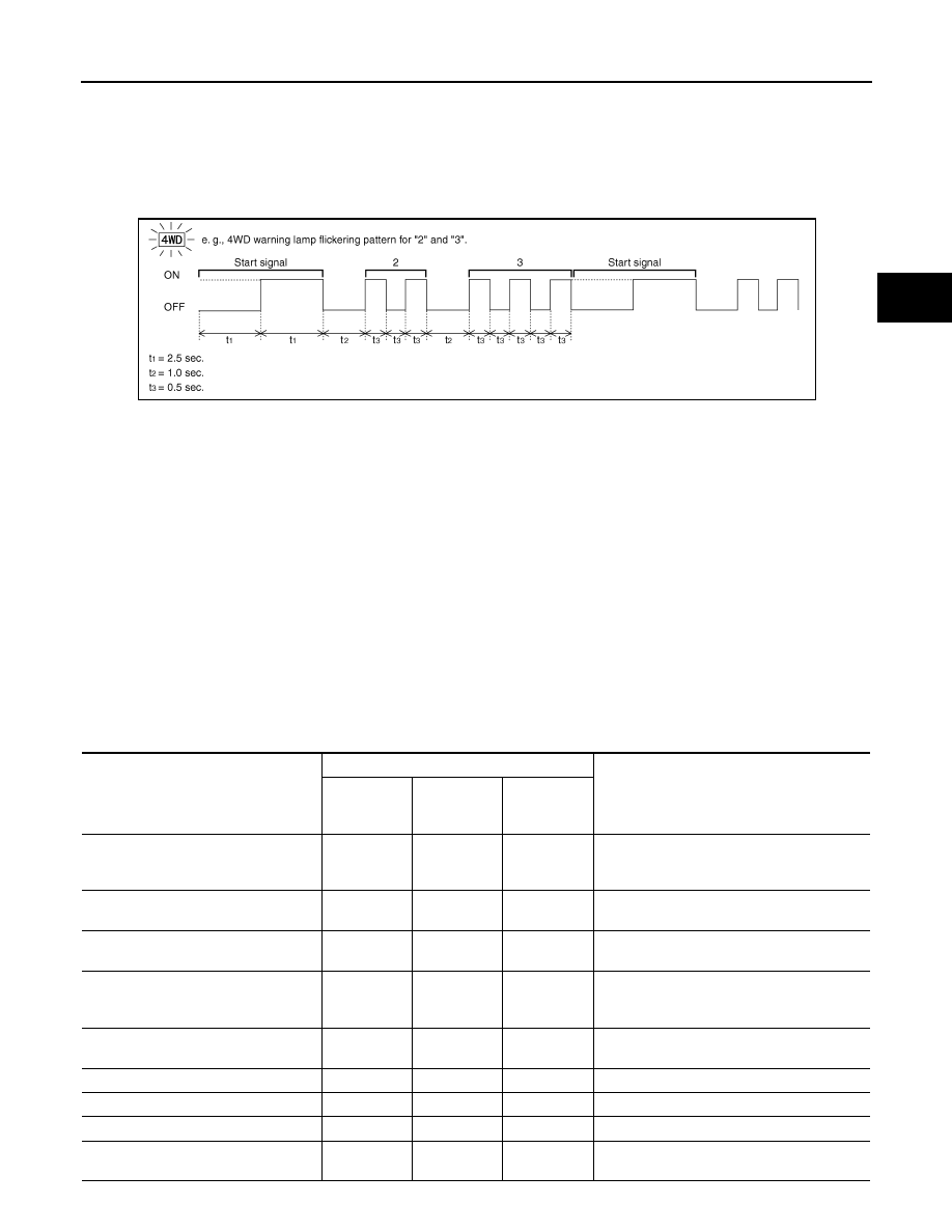
15. Read the flickering of 4WD warning lamp.
Self-diagnosis example
ERASE SELF-DIAGNOSIS
• In order to make it easier to find the cause of hard-to-duplicate malfunctions, malfunction information is
stored into the control unit as necessary during use by the user. This memory is not erased no matter how
many times the ignition switch is turned ON and OFF.
• However, this information is erased by turning ignition switch OFF after performing self-diagnostics or by
erasing the memory using the CONSULT-III.
DATA MONITOR MODE
Operation Procedure
1. Connect CONSULT-III.
2. Touch DATA MONITOR.
3. Select from SELECT MONITOR ITEM, screen of data monitor mode is displayed.
NOTE:
When malfunction is detected, CONSULT-III performs REAL-TIME DIAGNOSIS.
Also, any malfunction detected while in this mode will be displayed at real time.
Display Item List
×: Standard –: Not applicable
PDIA0227E
Monitored item (Unit)
Monitor item selection
Remarks
ECU INPUT
SIGNALS
MAIN
SIGNALS
SELEC-
TION FROM
MENU
VHCL/S SEN·FR [km/h] or [mph]
×
–
×
Wheel speed calculated by ABS actuator and
electric unit (control unit).
Signal input with CAN communication line.
VHCL/S SEN·RR [km/h] or [mph]
×
–
×
Wheel speed calculated by TCM.
Signal input with CAN communication line.
ENGINE SPEED [rpm]
×
–
×
Engine speed calculated by ECM.
Signal input with CAN communication line.
THRTL POS SEN [V]
×
–
×
Accelerator pedal position (APP) sensor sig-
nal voltage is displayed.
Signal input with CAN communication line.
FLUID TEMP SE [V]
×
–
×
Transfer fluid temperature sensor signal volt-
age is displayed.
BATTERY VOLT [V]
×
–
×
Power supply voltage for transfer control unit.
2WD SWITCH [On/Off]
×
–
×
4WD shift switch status is displayed.
AUTO SWITCH [On/Off]
×
–
×
4WD shift switch status is displayed.
LOCK SWITCH [On/Off]
×
–
×
4WD shift switch status is displayed.
(LOCK means 4H of 4WD shift switch.)