Infiniti QX56 (JA60). Manual - part 67
AV-76
< COMPONENT DIAGNOSIS >
[AUDIO SYSTEM]
POWER SUPPLY AND GROUND CIRCUIT
1. Turn ignition switch OFF.
2. Disconnect the video monitor connector R202 and the DVD
player connector M205.
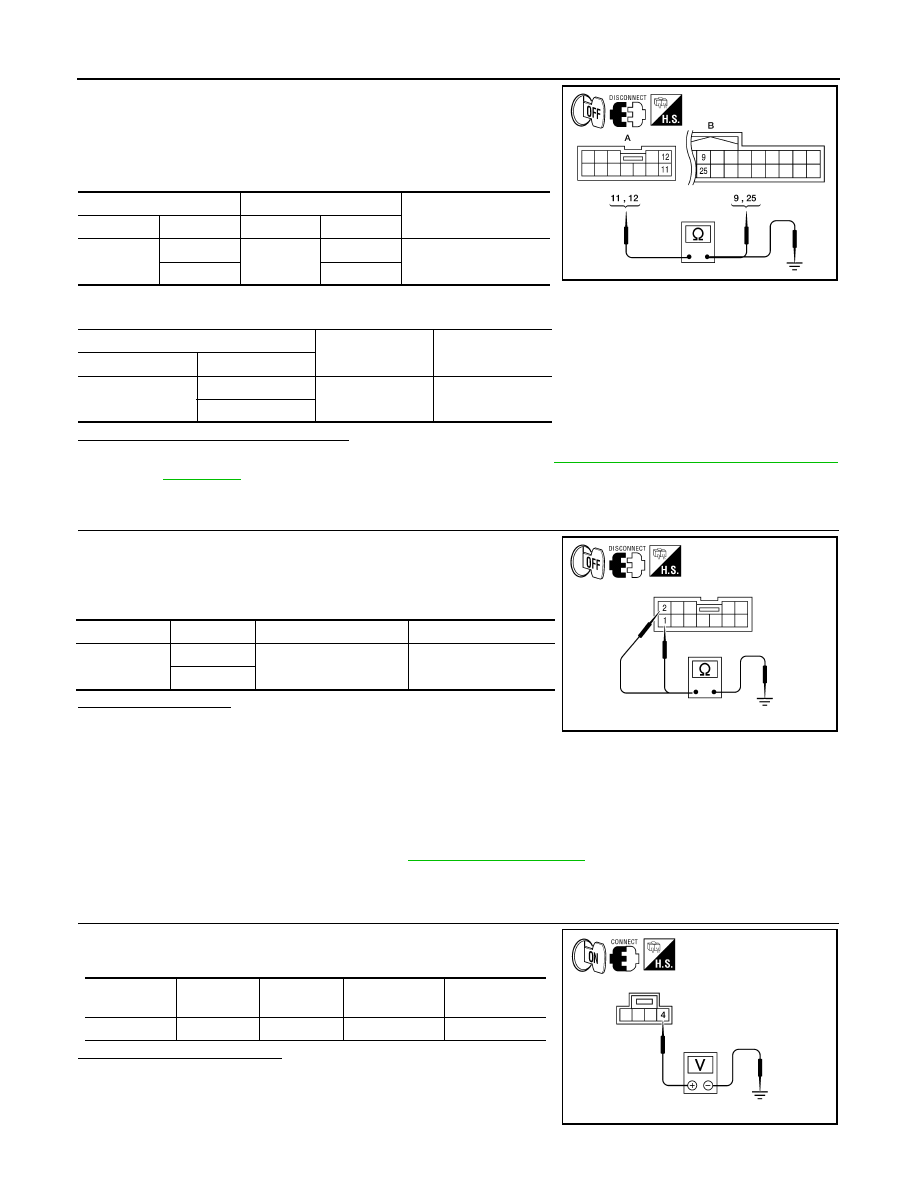
3. Check continuity between the video monitor harness connector
R202 (A) and the DVD player connector M205 (B).
4. Check continuity between video monitor harness connector R202 (A) and ground.
Are continuity test results as specified?
YES
>> Check DVD player power and ground supply. Refer to
AV-68, "AV CONTROL UNIT : Diagnosis
.
NO
>> Repair harness or connector.
3.
CHECK GROUND CIRCUIT
1. Turn ignition switch OFF.
2. Disconnect video monitor connector.
3. Check continuity between video monitor harness connector
R202 and ground.
Does continuity exist?
YES
>> Inspection end.
NO
>> Repair harness or connector.
MICROPHONE
MICROPHONE : Diagnosis Procedure
INFOID:0000000005146310
Regarding Wiring Diagram information, refer to
.
1.
CHECK POWER SUPPLY CIRCUIT
Check voltage between microphone harness connector R109 termi-
nal 4 and ground.
Is approximately 5V present?
YES
>> GO TO 3.
NO
>> GO TO 2.
A
B
Continuity
Connector
Terminal
Connector
Terminal
R202
11
M205
9
Yes
12
25
A
-
Continuity
Connector
Terminal
R202
11
Ground
No
12
AWLIA1600ZZ
Connector
Terminal
Ignition switch position
Continuity
R202
1
OFF
Yes
2
ALNIA0329GB
Signal name
Connector
Terminal
Ignition switch
position
Value (Approx.)
MIC power
R109
4
ON
5V
WKIA5796E