Infiniti QX56 (Z62). Manual - part 905


  Index      Infiniti     Infiniti QX56 (Z62) - service repair manual 2011 year


Search            


Content   ..  903  904  905  906   ..


Infiniti QX56 (Z62). Manual - part 905


LAN

MAIN LINE BETWEEN ADP AND PWBD CIRCUIT

LAN-197

< DTC/CIRCUIT DIAGNOSIS >

[CAN SYSTEM (TYPE 4)]

C

D

E

F

G

H

I

J

K

L

B

A

O

P

N

MAIN LINE BETWEEN ADP AND PWBD CIRCUIT

Diagnosis Procedure

INFOID:0000000006256369

1.

CHECK HARNESS CONTINUITY (OPEN CIRCUIT)

1.

Turn the ignition switch OFF.

2.

Disconnect the battery cable from the negative terminal.

3.

Disconnect the following harness connectors.

-

CAN gateway

-

Harness connectors B460 and B24

-

Automatic back door control module

4.

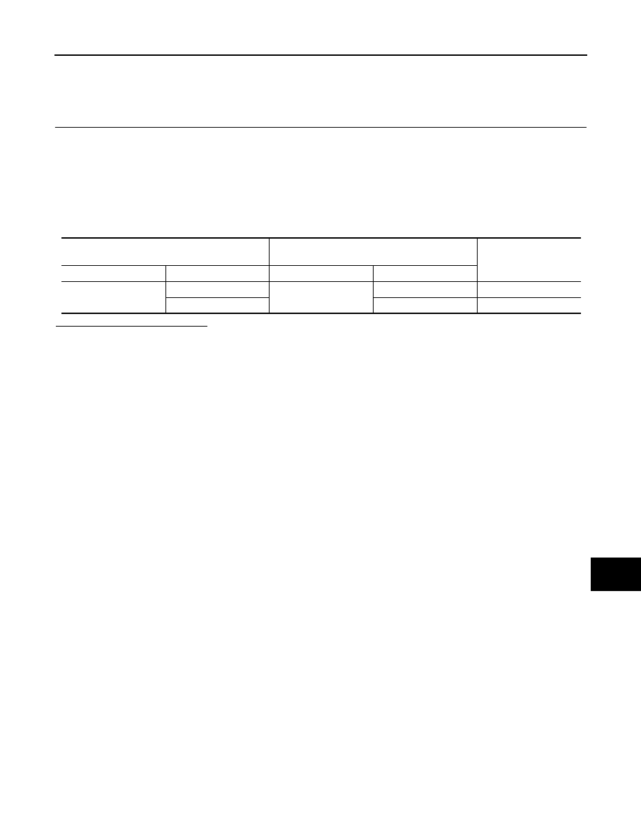
Check the continuity between the harness connector and the automatic back door control module harness
connector.

Is the inspection result normal?

YES (Present error)>>Check CAN system type decision again.
YES (Past error)>>Error was detected in the main line between the driver seat control unit and the automatic

back door control module. 

NO

>> Repair the main line between the harness connector B24 and the automatic back door control

module.

Harness connector

Automatic back door control module

harness connector

Continuity

Connector No.

Terminal No.

Connector No.

Terminal No.

B24

13

B26

7

Existed

12

6

Existed

LAN-198

< DTC/CIRCUIT DIAGNOSIS >

[CAN SYSTEM (TYPE 4)]

MAIN LINE BETWEEN RDR-R AND RDR-L CIRCUIT

MAIN LINE BETWEEN RDR-R AND RDR-L CIRCUIT

Diagnosis Procedure

INFOID:0000000006256370

1.

CHECK CONNECTOR

1.

Turn the ignition switch OFF.

2.

Disconnect the battery cable from the negative terminal.

3.

Check the following terminals and connectors for damage, bend and loose connection (connector side
and harness side).

-

Harness connector B239

-

Harness connector B63

Is the inspection result normal?

YES

>> GO TO 2.

NO

>> Repair the terminal and connector.

2.

CHECK HARNESS CONTINUITY (OPEN CIRCUIT)

1.

Disconnect the following harness connectors.

-

Side radar RH

-

Harness connectors B239 and B63

2.

Check the continuity between the side radar RH harness connector and the harness connector.

Is the inspection result normal?

YES

>> GO TO 3.

NO

>> Repair the main line between the side radar RH and the harness connector B239.

3.

CHECK HARNESS CONTINUITY (OPEN CIRCUIT)

1.

Disconnect the connector of side radar LH.

2.

Check the continuity between the harness connector and the side radar LH harness connector.

Is the inspection result normal?

YES (Present error)>>Check CAN system type decision again.
YES (Past error)>>Error was detected in the main line between the side radar RH and the side radar LH. 
NO

>> Repair the main line between the harness connector B63 and the side radar LH.

Side radar RH harness connector

Harness connector

Continuity

Connector No.

Terminal No.

Connector No.

Terminal No.

B243

4

B239

7

Existed

3

3

Existed

Harness connector

Side radar LH harness connector

Continuity

Connector No.

Terminal No.

Connector No.

Terminal No.

B63

7

B74

4

Existed

3

3

Existed

LAN

MAIN LINE BETWEEN RDR-L AND LANE CIRCUIT

LAN-199

< DTC/CIRCUIT DIAGNOSIS >

[CAN SYSTEM (TYPE 4)]

C

D

E

F

G

H

I

J

K

L

B

A

O

P

N

MAIN LINE BETWEEN RDR-L AND LANE CIRCUIT

Diagnosis Procedure

INFOID:0000000006256371

1.

CHECK CONNECTOR

1.

Turn the ignition switch OFF.

2.

Disconnect the battery cable from the negative terminal.

3.

Check the following terminals and connectors for damage, bend and loose connection (connector side
and harness side).

-

Harness connector B2

-

Harness connector M19

-

Harness connector M23

-

Harness connector R1

Is the inspection result normal?

YES

>> GO TO 2.

NO

>> Repair the terminal and connector.

2.

CHECK HARNESS CONTINUITY (OPEN CIRCUIT)

1.

Disconnect the following harness connectors.

-

Side radar LH

-

Harness connectors B2 and M19

2.

Check the continuity between the side radar LH harness connector and the harness connector.

Is the inspection result normal?

YES

>> GO TO 3.

NO

>> Repair the main line between the side radar LH and the harness connector B2.

3.

CHECK HARNESS CONTINUITY (OPEN CIRCUIT)

1.

Disconnect the harness connectors M23 and R1.

2.

Check the continuity between the harness connectors.

Is the inspection result normal?

YES

>> GO TO 4.

NO

>> Repair the main line between the harness connectors M19 and M23.

4.

CHECK HARNESS CONTINUITY (OPEN CIRCUIT)

1.

Disconnect the connector of lane camera unit.

2.

Check the continuity between the harness connector and the lane camera unit harness connector.

Is the inspection result normal?

YES (Present error)>>Check CAN system type decision again.
YES (Past error)>>Error was detected in the main line between the side radar LH and the lane camera unit. 

Side radar LH harness connector

Harness connector

Continuity

Connector No.

Terminal No.

Connector No.

Terminal No.

B74

4

B2

27

Existed

3

28

Existed

Harness connector

Harness connector

Continuity

Connector No.

Terminal No.

Connector No.

Terminal No.

M19

27

M23

26

Existed

28

23

Existed

Harness connector

Lane camera unit harness connector

Continuity

Connector No.

Terminal No.

Connector No.

Terminal No.

R1

26

R8

4

Existed

23

8

Existed

LAN-200

< DTC/CIRCUIT DIAGNOSIS >

[CAN SYSTEM (TYPE 4)]

MAIN LINE BETWEEN RDR-L AND LANE CIRCUIT

NO

>> Repair the main line between the harness connector R1 and the lane camera unit.


Content   ..  903  904  905  906   ..