Content .. 1169 1170 1171 1172 ..
Infiniti QX56 (Z62). Manual - part 1171
SEC-74
< DTC/CIRCUIT DIAGNOSIS >
[WITH INTELLIGENT KEY SYSTEM]
B2555 STOP LAMP
Is the inspecting result normal?
YES
>> GO TO 4.
NO
>> GO TO 5.
4.
REPLACE BCM
1.
Replace BCM. Refer to
BCS-81, "Removal and Installation"
.
2.
Perform initialization of BCM and registration of all Intelligent Keys using CONSULT-III.
For initialization and registration procedures, refer to CONSULT-III Operation Manual NATS-IVIS/NVIS.
>> INSPECTION END
5.
CHECK STOP LAMP SWITCH CIRCUIT
1.
Disconnect stop lamp switch connector.
2.
Check continuity between stop lamp switch harness connector and BCM harness connector.
3.
Check continuity between stop lamp switch harness connector and ground.
Is the inspection result normal?
YES
>> GO TO 6.
NO
>> Repair or replace harness.
6.
CHECK STOP LAMP SWITCH
SEC-74, "Component Inspection"
.
Is the inspection result normal?
YES
>> GO TO 7.
NO
>> Replace stop lamp switch. Refer to
BR-20, "Removal and Installation"
.
7.
CHECK INTERMITTENT INCIDENT
GI-40, "Intermittent Incident"
>> INSPECTION END
Component Inspection
INFOID:0000000006226224
1.
CHECK STOP LAMP SWITCH
1.
Turn ignition switch OFF.
2.
Disconnect stop lamp switch connector.
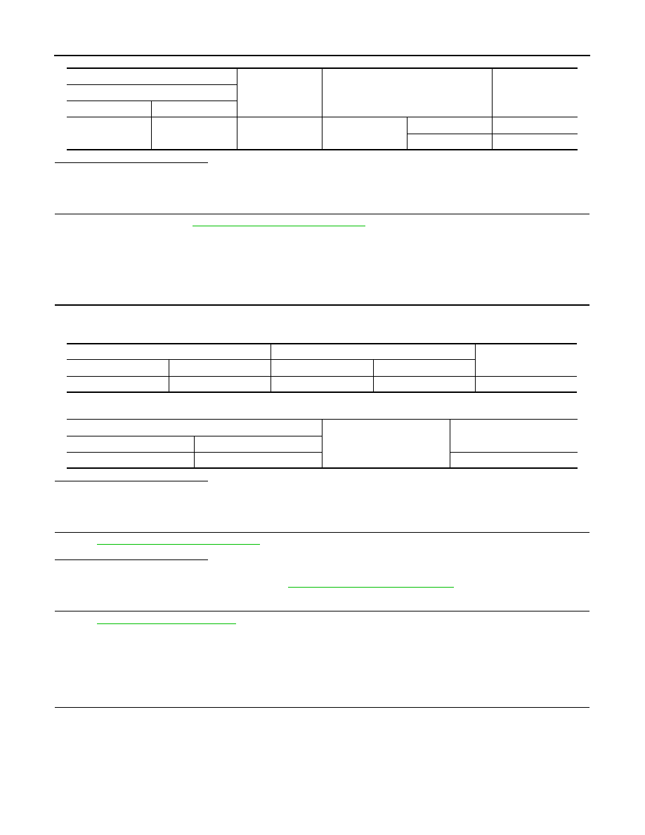
3.
Check continuity between stop lamp switch terminals.
(+)
(–)
Condition
Voltage (V)
(Approx.)
BCM
Connector
Terminal
M68
9
Ground
Brake pedal
Depressed
Battery voltage
Not depressed
0
Stop lamp switch
BCM
Continuity
Connector
Terminal
Connector
Terminal
E115
2
M68
9
Existed
Stop lamp switch
Ground
Continuity
Connector
Terminal
E115
2
Not existed