Infiniti QX56 (Z62). Manual - part 1031


  Index      Infiniti     Infiniti QX56 (Z62) - service repair manual 2011 year


Search            


Content   ..  1029  1030  1031  1032   ..


Infiniti QX56 (Z62). Manual - part 1031


PWC-36

< DTC/CIRCUIT DIAGNOSIS >

POWER SUPPLY AND GROUND CIRCUIT

Refer to 

GI-40, "Intermittent Incident"

.

>> INSPECTION END

FRONT POWER WINDOW SWITCH (PASSENGER SIDE)

FRONT POWER WINDOW SWITCH (PASSENGER SIDE) : Diagnosis Procedure

INFOID:0000000006217291

1.

CHECK POWER SUPPLY 

1.

Turn ignition switch OFF.

2.

Disconnect front power window switch (passenger side) connector.

3.

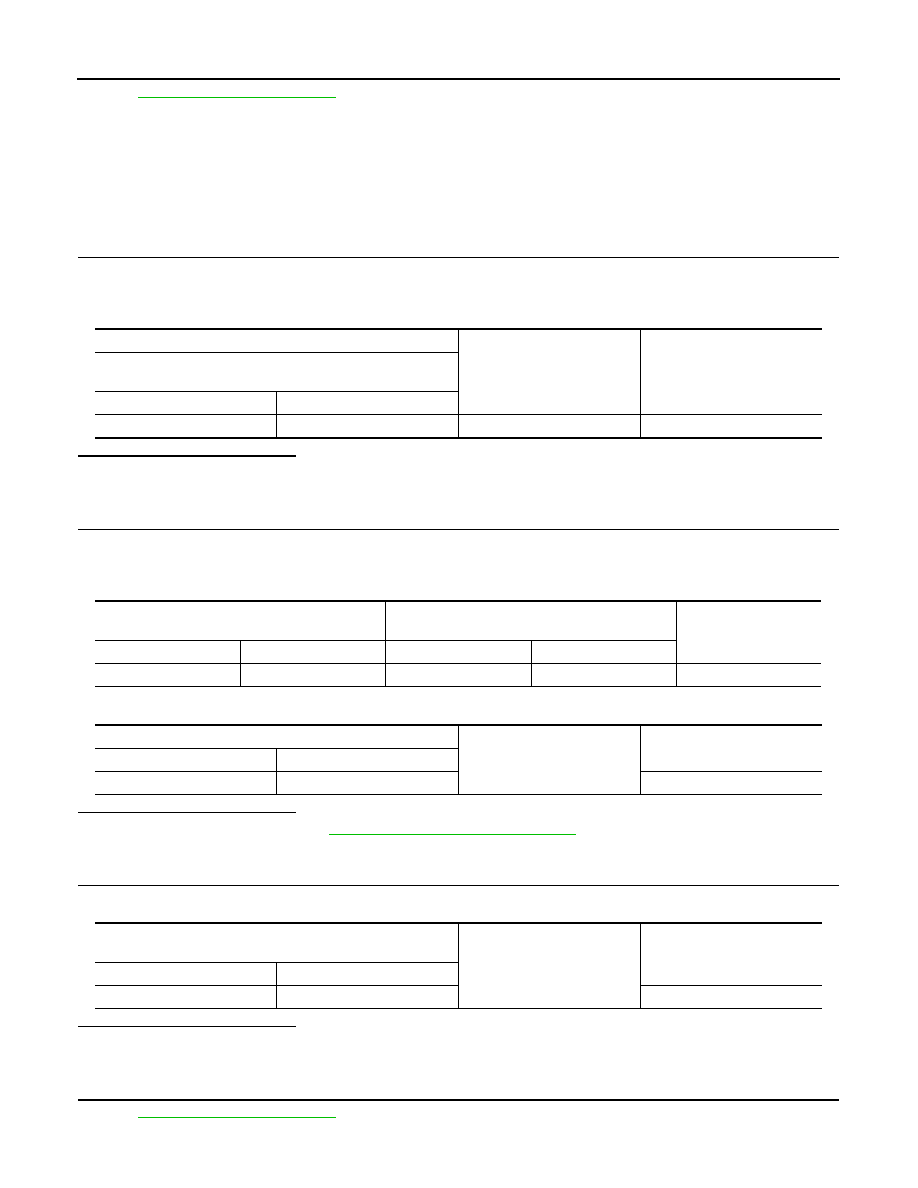
Check voltage between front power window switch (passenger side) harness connector and ground.

Is the inspection result normal?

YES

>> GO TO 3.

NO

>> GO TO 2.

2.

CHECK POWER SUPPLY CIRCUIT

1.

Disconnect BCM connector.

2.

Check continuity between BCM harness connector and front power window switch (passenger side) har-
ness connector.

3.

Check continuity between BCM harness connector and ground.

Is the inspection result normal?

YES

>> Replace BCM. Refer to 

BCS-81, "Removal and Installation"

.

NO

>> Repair or replace harness.

3.

CHECK GROUND CIRCUIT

Check continuity between front power window switch (passenger side) harness connector and ground.

Is the inspection result normal?

YES

>> GO TO 4.

NO

>> Repair or replace harness.

4.

CHECK INTERMITTENT INCIDENT

Refer to 

GI-40, "Intermittent Incident"

.

(+)

(–)

Voltage (V)

(Approx.)

Front power window switch 

(passenger side)

Connector

Terminal

D25

10

Ground

12

BCM

Front power window switch

(passenger side)

Continuity

Connector

Terminal

Connector

Terminal

M70

69

D25

10

Existed

BCM

Ground

Continuity

Connector

Terminal

M70

69

Not existed

Front power window switch

(passenger side)

Ground

Continuity 

Connector

Terminal

D25

11

Existed

POWER SUPPLY AND GROUND CIRCUIT

PWC-37

< DTC/CIRCUIT DIAGNOSIS >

C

D

E

F

G

H

I

J

L

M

A

B

PWC

N

O

P

>> INSPECTION END

REAR POWER WINDOW SWITCH

REAR POWER WINDOW SWITCH : Diagnosis Procedure

INFOID:0000000006217292

1.

CHECK POWER SUPPLY

1.

Turn ignition switch OFF.

2.

Disconnect rear power window switch LH connector and rear power window switch RH connector.

3.

Turn ignition switch ON.

4.

Check voltage between rear power window switch harness connector and ground.

Is the inspection result normal?

YES

>> GO TO 3.

NO

>> GO TO 2.

2.

CHECK POWER SUPPLY CIRCUIT

1.

Turn ignition switch OFF.

2.

Disconnect BCM connector.

3.

Check continuity between BCM harness connector and rear power window switch harness connector.

4.

Check continuity between BCM harness connector and ground.

Is the inspection result normal?

YES

>> Replace BCM. Refer to 

BCS-81, "Removal and Installation"

.

NO

>> Repair or replace harness.

3.

CHECK GROUND CIRCUIT

1.

Turn ignition switch OFF.

2.

Check continuity between rear power window switch harness connector and ground.

Is the inspection result normal?

YES

>> GO TO 4.

NO

>> Repair or replace harness.

4.

CHECK INTERMITTENT INCIDENT

Refer to 

GI-40, "Intermittent Incident"

.

(+)

(–)

Voltage (V)

(Approx.)

Rear power window switch

Connector Terminal

LH

D63

10

Ground

12

RH

D43

BCM

Rear power window switch 

Continuity

Connector

Terminal

Connector

Terminal

M70

69

LH

D63

10

Existed

RH

D43

BCM

Ground

Continuity

Connector

Terminal

M70

69

Not existed

Rear power window switch 

Ground

Continuity 

Connector

Terminal

LH

D63

11

Existed

RH

D43

PWC-38

< DTC/CIRCUIT DIAGNOSIS >

POWER SUPPLY AND GROUND CIRCUIT

>> INSPECTION END

POWER WINDOW MOTOR

PWC-39

< DTC/CIRCUIT DIAGNOSIS >

C

D

E

F

G

H

I

J

L

M

A

B

PWC

N

O

P

POWER WINDOW MOTOR

DRIVER SIDE

DRIVER SIDE : Component Function Check

INFOID:0000000006217293

1.

CHECK POWER WINDOW MOTOR CIRCUIT

Check front power window motor (driver side) operation with power window main switch.

Is the inspection result normal?

YES

>> Front power window motor (driver side) is OK.

NO

>> Refer to 

PWC-39, "DRIVER SIDE : Diagnosis Procedure"

.

DRIVER SIDE : Diagnosis Procedure

INFOID:0000000006217294

1.

CHECK FRONT POWER WINDOW MOTOR INPUT SIGNAL

1.

Turn ignition switch OFF.

2.

Disconnect front power window motor (driver side) connector.

3.

Turn ignition switch ON.

4.

Check voltage between front power window motor (driver side) harness connector and ground.

Is the inspection result normal?

YES

>> Replace  front power window motor (driver side). Refer to 

GW-21, "Removal and Installation"

.

NO

>> GO TO 2.

2.

CHECK POWER WINDOW MOTOR CIRCUIT

1.

Turn ignition switch OFF.

2.

Disconnect power window main switch connector.

3.

Check continuity between power window main switch harness connector and front power window motor
(driver side) harness connector.

4.

Check continuity between power window main switch harness connector and ground.

Is the inspection result normal?

YES

>> Replace power window main switch. Refer to 

PWC-74, "Removal and Installation"

.

NO

>> Repair or replace harness.

PASSENGER SIDE

(+)

(–)

Condition

Voltage (V)

(Approx.)

Front power window motor (driver side)

Connector

Terminal

D7

3

Ground

Power window main switch

 UP

12

DOWN

0

1

UP

0

 DOWN

12

Power window main switch

Front power window motor

 (driver side) 

Continuity

Connector

Terminal

Connector

Terminal

D5

8

D7

3

Existed

11

1

Power window main switch

Ground

Continuity

Connector

Terminal

D5

8

Not existed

11


Content   ..  1029  1030  1031  1032   ..