Infiniti QX4 (R50). Manual - part 484
3
CHECK IN-VEHICLE SENSOR
Refer to HA-135.
OK or NG
OK
©
1. Replace auto amp.
2. Go to self-diagnosis step-by-step procedure (HA-45) and perform self-diagnosis STEP
2.
Confirm that code No. 20 is displayed.
NG
©
1. Replace in-vehicle sensor.
2. Go to self-diagnosis step-by-step procedure (HA-45) and perform self-diagnosis STEP
2.
Confirm that code No. 20 is displayed.
4
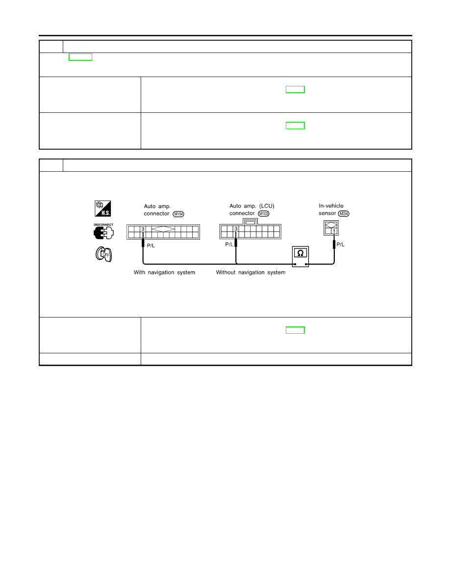
CHECK IN-VEHICLE SENSOR CIRCUIT BETWEEN AMBIENT SENSOR AND AUTO AMP. (LCU)
1. Disconnect auto amp. (LCU) harness connector.
2. Check circuit continuity between in-vehicle sensor harness terminal No. 1 and auto amp. (LCU) harness terminal No. 3.
RHA832H
Continuity should exist.
If OK, check harness for short.
OK or NG
OK
©
1. Replace auto amp. (LCU).
2. Go to self-diagnosis step-by-step procedure (HA-45) and perform self-diagnosis STEP
2.
Confirm that code No. 20 is displayed.
NG
©
Repair harness or connector.
TROUBLE DIAGNOSES
In-vehicle Sensor Circuit (Cont’d)
HA-134