Infiniti QX4 (R50). Manual - part 424
SEM869EA
4.
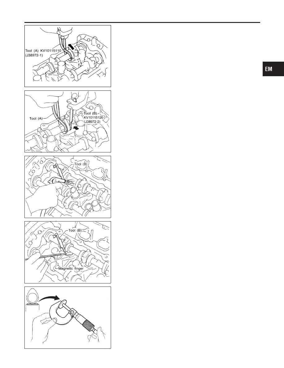
Place Tool (A) around camshaft as shown in figure.
Before placing Tool (A), rotate notch toward center of cyl-
inder head (See figure.), to simplify shim removal later.
CAUTION:
Be careful not to damage cam surface with Tool (A).
5.
Rotate Tool (A) (See figure.) so that valve lifter is pushed down.
SEM870E
6.
Place Tool (B) between camshaft and the edge of the valve
lifter to retain valve lifter.
CAUTION:
I
Tool (B) must be placed as close to camshaft bracket as
possible.
I
Be careful not to damage cam surface with Tool (B).
7.
Remove Tool (A).
SEM871E
8.
Blow air into the hole to separate adjusting shim from valve
lifter.
SEM872E
SEM145D
9.
Remove adjusting shim using a small screwdriver and a mag-
netic finger.
10. Determine replacement adjusting shim size following formula.
I
Using a micrometer determine thickness of removed shim.
I
Calculate thickness of new adjusting shim so valve clearance
comes within specified values.
R = Thickness of removed shim
N = Thickness of new shim
M = Measured valve clearance
Intake:
N = R + [M − 0.30 mm (0.0118 in)]
Exhaust:
N = R + [M − 0.33 mm (0.0130 in)]
Shims are available in 64 sizes from 2.32 mm (0.0913 in)
to 2.95 mm (0.1161 in), in steps of 0.01 mm (0.0004 in).
I
Select new shim with thickness as close as possible to calcu-
lated value.
GI
MA
LC
EC
FE
AT
TF
PD
AX
SU
BR
ST
RS
BT
HA
SC
EL
IDX
CYLINDER HEAD
Valve Clearance (Cont’d)
EM-55