Infiniti QX4 (R50). Manual - part 175
Diagnostic Procedure
NBEC0068
1
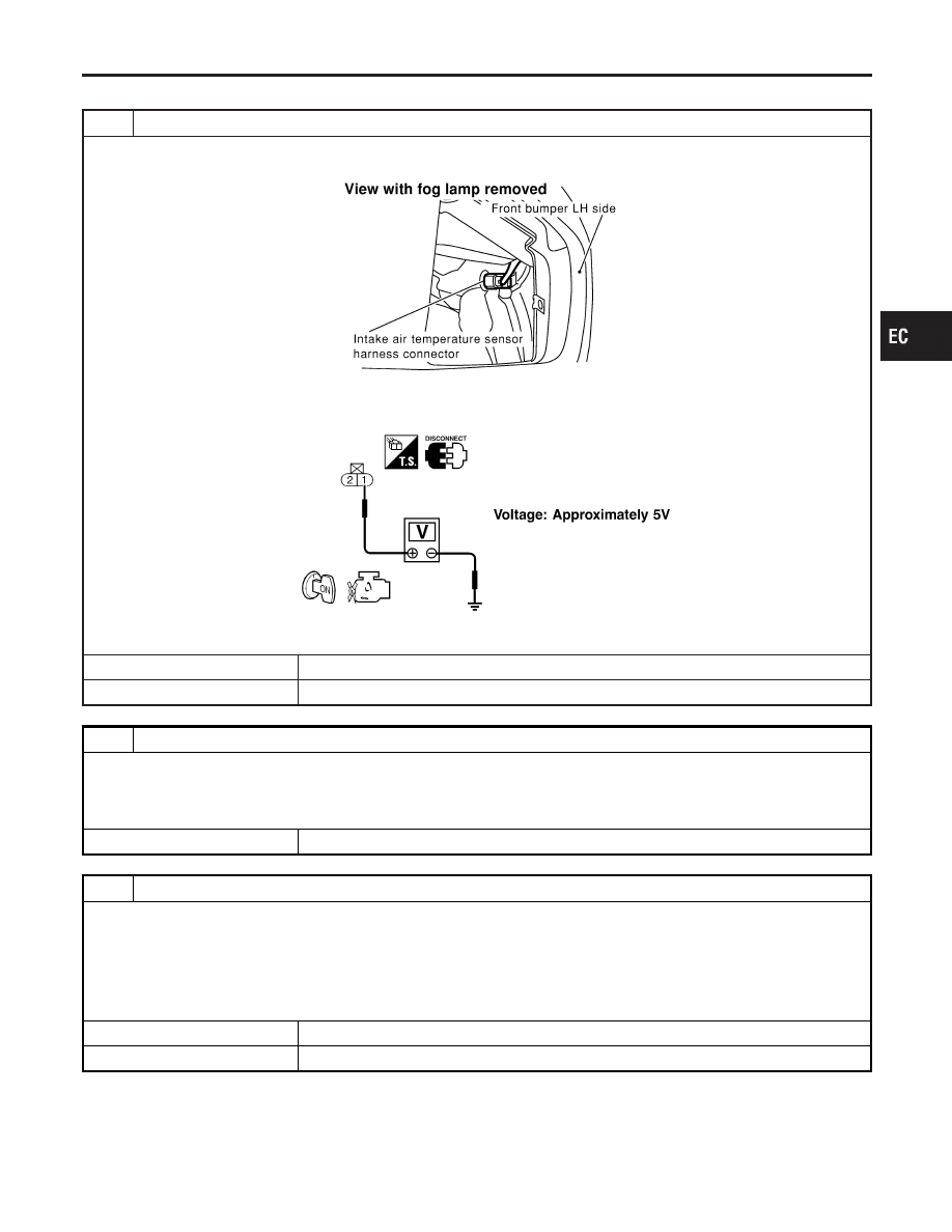
CHECK INTAKE AIR TEMPERATURE SENSOR POWER SUPPLY CIRCUIT
1. Turn ignition switch “OFF”.
2. Disconnect intake air temperature sensor harness connector.
SEF962Y
3. Turn ignition switch “ON”.
4. Check voltage between terminal 1 and ground.
SEF301X
OK or NG
OK
©
GO TO 3.
NG
©
GO TO 2.
2
DETECT MALFUNCTIONING PART
Check the following.
I
Harness connectors E1, M1
I
Harness connectors M33, F22
I
Harness for open or short between ECM and intake air temperature sensor
©
Repair harness or connectors.
3
CHECK INTAKE AIR TEMPERATURE SENSOR GROUND CIRCUIT FOR OPEN AND SHORT
1. Turn ignition switch “OFF”.
2. Check harness continuity between sensor terminal 2 and engine ground.
Refer to Wiring Diagram.
Continuity should exist.
3. Also check harness for short to power.
OK or NG
OK
©
GO TO 5.
NG
©
GO TO 4.
GI
MA
EM
LC
FE
AT
TF
PD
AX
SU
BR
ST
RS
BT
HA
SC
EL
IDX
DTC P0110 INTAKE AIR TEMPERATURE SENSOR
Diagnostic Procedure
EC-167