Index Infiniti Infiniti Q45 - service repair manual 2006 year
Search copyright infringement
Content .. 875 876 877 878 ..
Infiniti Q45. Manual - part 877
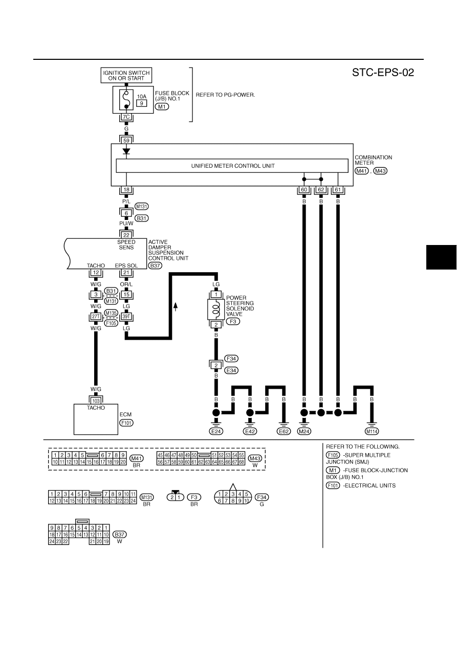
TROUBLE DIAGNOSIS
STC-11
[WITHOUT REAR ACTIVE STEER]
C
D
E
F
H
I
J
K
L
M
A
B
STC
TGWM0076E