Infiniti M45 (Y34). Manual - part 319
VEHICLE INFORMATION AND INTEGRATED SWITCH SYSTEM /WITHOUT
NAVIGATION SYSTEM
DI-121
C
D
E
F
G
H
I
J
L
M
A
B
DI
Power Supply and Ground Circuit Inspection for Display
AKS004OJ
1.
CHECK FUSES
Check the followings.
●
15A fuse [No. 52, located in fuse, fusible link and relay block (J/B)] is blown
●
10A fuse [No. 21, located in fuse block (J/B) NO. 1] is blown
OK or NG
OK
>> GO TO 2.
NG
>> If fuse is blown, be sure to eliminate cause of malfunction before installing new fuse. Refer to
2.
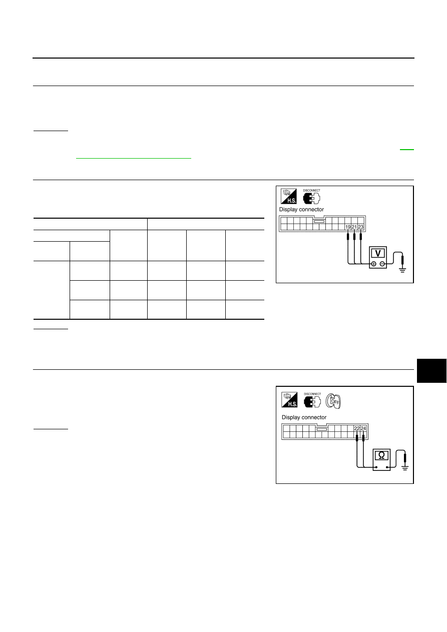
CHECK POWER SUPPLY CIRCUIT
1.
Disconnect display connector.
2.
Check voltage between display harness connector M82 termi-
nals and ground.
OK or NG
OK
>> GO TO 3.
NG
>> Check harness for open or short between display and fuse.
3.
CHECK GROUND CIRCUIT
1.
Turn ignition switch OFF.
2.
Check continuity between display harness connector M82 termi-
nals 22 (B), 24 (B) and ground.
OK or NG
OK
>> Inspection end.
NG
>> Repair harness or connector.
Terminals
Ignition switch position
(+)
(–)
OFF
ACC
ON
Connector
Terminal
(Wire color)
M82
19 (L/B)
Ground
0V
Battery
voltage
Battery
voltage
21 (SB)
Ground
Battery
voltage
Battery
voltage
Battery
voltage
23 (SB)
Ground
Battery
voltage
Battery
voltage
Battery
voltage
SKIA0552E
Continuity should exist.
SKIA0553E