Infiniti M35/M45 Y50. Manual - part 994
FRONT PROPELLER SHAFT
PR-5
C
E
F
G
H
I
J
K
L
M
A
B
PR
Removal and Installation
NDS000EC
REMOVAL
1.
Remove engine undercover with a power tool.
2.
If necessary, remove heat bracket.
3.
Remove the three way catalyst (right bank) with a power tool. Refer to
4.
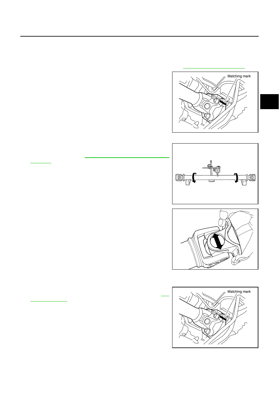
Put matching marks onto propeller shaft flange yoke and final
drive companion flange.
CAUTION:
For matching marks, use paint. Do not damage propeller
shaft flange and companion flange.
5.
Remove the propeller shaft fixing bolts.
6.
Remove propeller shaft from the front final drive and transfer.
INSPECTION
●
Inspect propeller shaft runout at measuring point. If runout
exceeds specifications, replace propeller shaft assembly. For
measuring point, refer to
PR-4, "Propeller Shaft Runout Measur-
●
As shown in the figure, while fixing yoke on one side, check axial
play of joint. If outside the standard, replace propeller shaft
assembly.
●
Check propeller shaft for bend and damage. If damage is
detected, replace propeller shaft assembly.
CAUTION:
Do not disassemble joints.
INSTALLATION
Note the following, install in the reverse order of removal.
●
Align matching marks to install propeller shaft to final drive com-
panion flange, and then tighten to specified torque. Refer to
CAUTION:
Do not reuse the bolts.
●
After assembly, perform a driving test to check propeller shaft
vibration. If vibration occurred, separate propeller shaft from
final drive or transfer. Reinstall companion flange after rotating it
by 90, 180, 270 degrees. Then perform driving test and check
propeller shaft vibration again at each point.
SDIA1517E
Propeller shaft runout limit
: 0.8 mm (0.031 in)
SPD106
Journal axial play
: 0 mm (0 in)
PDA0005D
SDIA1517E