Infiniti M35/M45 Y50. Manual - part 377
 

  Index      Infiniti     Infiniti M35/M45 Y50 - service repair manual 2007 year


Search            copyright infringement  


Content   ..  375  376  377  378   ..


Infiniti M35/M45 Y50. Manual - part 377


LANE DEPARTURE WARNING SYSTEM

DI-91

C

D

E

F

G

H

I

J

L

M

A

B

DI

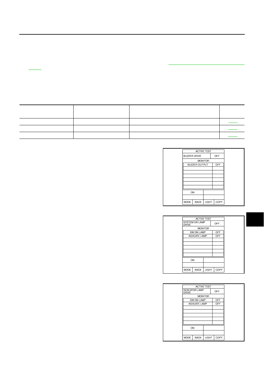
ACTIVE TEST

CAUTION:

Never perform the active test while driving.

Active test cannot be started while LDW indicator lamp is illuminated.

1.

Touch “ACTIVE TEST” on “SELECT DIAG MODE” screen. Refer to 

DI-88, "CONSULT-II BASIC OPERA-

TION"

 .

2.

Touch any field, “BUZZER DRIVE ”, “SYSTEM ON LAMP DRIVE” and “INDICATOR LAMP DRIVE”, on
selection screen.

3.

Touch necessary item and “START”.

4.

Active test screen will be shown.

Display Item List

BUZZER DRIVE

Touch “ON” and “OFF” to check if LDW chime operates as follows.

SYSTEM ON LAMP DRIVE

Touch “ON” and “OFF” to check if LDW system ON indicator oper-
ates as follows.

NOTE:
Perform “SYSTEM ON LAMP DRIVE” when LDW system ON indica-
tor turns OFF.

INDICATOR LAMP DRIVE

Touch “ON” and “OFF” to check that LDW indicator lamp operates as
follows.

Display item

Operation item

Function

Reference 

page

BUZZER DRIVE

LDW chime

Checks LDW chime operation.


DI-91

SYSTEM ON LAMP DRIVE

LDW system ON indicator

Checks LDW system ON indicator operation.

DI-91

INDICATOR LAMP DRIVE

LDW indicator lamp

Checks LDW indicator lamp operation.

DI-91

“BUZZER DRIVE”

Touch “ON”

: LDW chime is activated.

Touch “OFF”

: LDW chime is not activated.

SKIB1787E

“SYSTEM ON LAMP DRIVE”

Touch “ON”

: LDW system ON indicator illuminates.

Touch “OFF”

: LDW system ON indicator turns OFF.

SKIB1788E

“INDICATOR LAMP DRIVE”

Touch “ON”

: LDW indicator lamp illuminates.

Touch “OFF”

: LDW indicator lamp OFF.

PKIB4692E

DI-92

LANE DEPARTURE WARNING SYSTEM

Trouble Diagnosis

NKS003VN

HOW TO PERFORM TROUBLE DIAGNOSIS

1.

Check the symptom and customer complaint.

2.

Understand the outline of system. Refer to 

DI-75, "System Description"

 .

3.

Perform the preliminary inspection. Refer to 

DI-92, "PRELIMINARY INSPECTION"

 .

4.

Referring to symptom chart, make sure the cause of the malfunction and repair or replace applicable
parts. Refer to 

DI-93, "SYMPTOM CHART"

 .

5.

Erase DTC and perform self-diagnosis of LDW system again. Then perform LDW system running test.
Refer to 

DI-88, "CONSULT-II Function (LDW)"

  and 

DI-77, "LDW SYSTEM RUNNING TEST"

 .

6.

Does LDW system operate normally? If yes, GO TO 7. If no, GO TO 3.

7.

INSPECTION END

PRELIMINARY INSPECTION

1. 

CHECK CAMERA LENS AND WINDSHIELD

Are camera lens and windshield contaminated with foreign materials? 

YES

>> Clean camera lens and windshield.

NO

>> GO TO 2.

2. 

CHECK CAMERA UNIT INSTALLATION CONDITION

Check camera unit installation condition (installation position, properly tightened, a bent bracket). 

OK or NG

OK

>> GO TO 3.

NG

>> Install camera unit properly, and adjust camera aiming. Refer to 

DI-78, "Camera Aiming Adjust-

ment"

 .

3. 

CHECK VEHICLE HEIGHT

Check vehicle height. Refer to 

FSU-19, "SERVICE DATA AND SPECIFICATIONS (SDS)"

  (2WD) or 

FSU-37,

"SERVICE DATA AND SPECIFICATIONS (SDS)"

  (AWD).

Is vehicle height appropriate?

OK

>> GO TO 4.

NG

>> Repair vehicle to appropriate height.

4. 

CHECK LDW CAMERA UNIT (CONSULT-II)

Perform self-diagnosis of LDW camera unit. Refer to 

DI-88, "CONSULT-II Function (LDW)"

 .

Self-diagnostic results content

No malfunction detected>>GO TO 5.
Malfunction detected>>Check applicable parts, and repair or replace corresponding parts.

5. 

CHECK COMBINATION METER

Check combination meter function.
Do speedometer and turn signal indicator function normally?

YES

>> INSPECTION END

NO

>> Check combination meter. Refer to 

DI-18, "Trouble Diagnosis"

 .

LANE DEPARTURE WARNING SYSTEM

DI-93

C

D

E

F

G

H

I

J

L

M

A

B

DI

SYMPTOM CHART

Power Supply and Ground Circuit Inspection

NKS003VO

1. 

CHECK FUSE

Check for blown LDW camera unit fuse.

OK or NG

OK

>> GO TO 2.

NG

>> Be sure to eliminate cause of malfunction before installing new fuse. Refer to 

PG-3, "POWER

SUPPLY ROUTING CIRCUIT"

 .

2. 

CHECK POWER SUPPLY CIRCUIT

Check voltage between LDW camera unit and ground.

OK or NG

OK

>> GO TO 3.

NG

>> Check harness between LDW camera unit and fuse.

Symptom

Diagnosis/Service procedure

LDW system is not activated.
(LDW system ON indicator turns ON/OFF.)

Perform the following inspections.

1.

DI-95, "LDW Chime Circuit Inspection"

2.

DI-99, "LDW Indicator Lamp Circuit Inspection"

Replace LDW camera unit, found normal function in the above inspections. 

LDW system does not turn ON/OFF.
(LDW system ON indicator does not turn ON/OFF.)

Perform 

DI-96, "LDW Switch Circuit Inspection"

 .

Replace LDW camera unit, found normal function in the above inspection. 

Warning functions are untimely.

(Example)

Warning does not function when driving on lane mark-
ers.

Warning functions when driving in a lane.

Differs position from actual condition functions.

Perform 

DI-78, "Camera Aiming Adjustment"

 .

Functions when changing the course to the turn signal 
direction.

Perform 

DI-100, "Turn Signal Input Inspection"

 .

Replace LDW camera unit, found normal function in the above inspection. 

LDW indicator lamp does not illuminate with ignition 
switch ON.

Perform 

DI-99, "LDW Indicator Lamp Circuit Inspection"

 .

Replace LDW camera unit, found normal function in the above inspection. 

Unit

Power source

Fuse No.

LDW camera unit

Ignition switch ON or START 

12

Terminals

Ignition switch position

(+)

(–)

OFF

ON

LDW camera 

unit connector

Terminal

M182

1

Ground

0 V

Battery voltage

PKIC0246E

DI-94

LANE DEPARTURE WARNING SYSTEM

3. 

CHECK GROUND CIRCUIT

1.

Turn ignition switch OFF.

2.

Disconnect LDW camera unit connector.

3.

Check continuity between LDW camera unit harness connector
and ground.

OK or NG

OK

>> Power supply and ground circuit are OK.

NG

>> Repair ground harness.

DTC [C1B00] CAMERA UNIT MALF

NKS003VP

1. 

CHECK LDW CAMERA UNIT

1.

Perform self-diagnosis of LDW camera unit.

2.

Check if any item other than “[C1B00] CAMERA UNIT” is displayed on self-diagnosis display.

Is any displayed?

YES

>> Repair or replace applicable item.

NO

>> Replace LDW camera unit.

DTC [C1B01] CAM AIMING INCMP

NKS003VQ

1. 

PREFORM CAMERA AIMING ADJUSTMENT

1.

Preform camera aiming adjustment. Refer to 

DI-78, "Camera Aiming Adjustment"

 .

2.

Erase DTC and perform LDW camera unit self-diagnosis.

Self-diagnostic results content

No malfunction detected>>INSPECTION END
Malfunction detected>>Replace LDW camera unit.

DTC [C1B02] VHCL SPD DATA MALF

NKS003VR

1. 

CHECK ABS ACTUATOR AND ELECTRIC UNIT (CONTROL UNIT) {CONSULT-II}

Perform ABS actuator and electric unit (control unit) self-diagnosis. Refer to 

BRC-23, "CONSULT-II Functions

(ABS)"

 .

Self-diagnostic results content

No malfunction detected>>GO TO 2.
Malfunction detected>>Check applicable parts, and repair or replace corresponding parts.

2. 

CHECK TCM (CONSULT-II)

Perform TCM self-diagnosis. Refer to 

AT-90, "CONSULT-II Function (A/T)"

 .

Self-diagnostic results content

No malfunction detected>>Replace LDW camera unit.
Malfunction detected>>Check applicable parts, and repair or replace corresponding parts.

DTC [C1B03] ABNRML TEMP DETECT

NKS003VS

1. 

COOLING CAMERA UNIT

1.

Cooling camera unit.

2.

Erase DTC and perform LDW camera unit self-diagnosis.

Self-diagnostic results content

No malfunction detected>>INSPECTION END
Malfunction detected>>Replace LDW camera unit.

LDW camera unit connector

Terminal

Ground

Continuity

M182

6

Yes

12

PKIC0247E


Content   ..  375  376  377  378   ..